Sparton 1568
After a lot of web research I found a few schematics that I liked from the JE Labs website (now offline) and Angela Instruments.
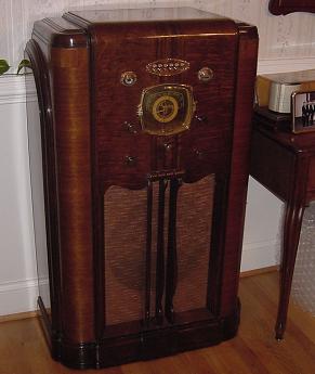
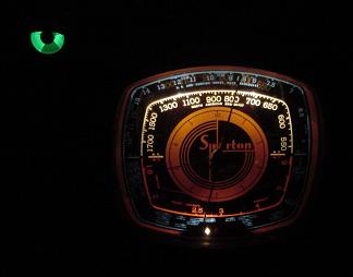
After restoring a nice old 1938 Sparton Model 1568 console radio,
I was so impressed with the quality of the sound that I started
looking into building an amplifier using the same 2A3 output tubes
that the big console uses.
Sparton 1568
After a lot of web research I found a few schematics that I liked
from the JE Labs website (now offline) and Angela Instruments.
The first one was the 2001 version using a 6SL7 driver and the
2A3 output. Here is that schematic:
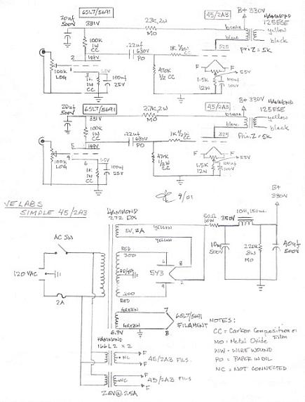
The above version only used one stage of amplification ahead of
the 2A3, and the next version used both halves of the 6SL7 as a 2
stage preamplifier.
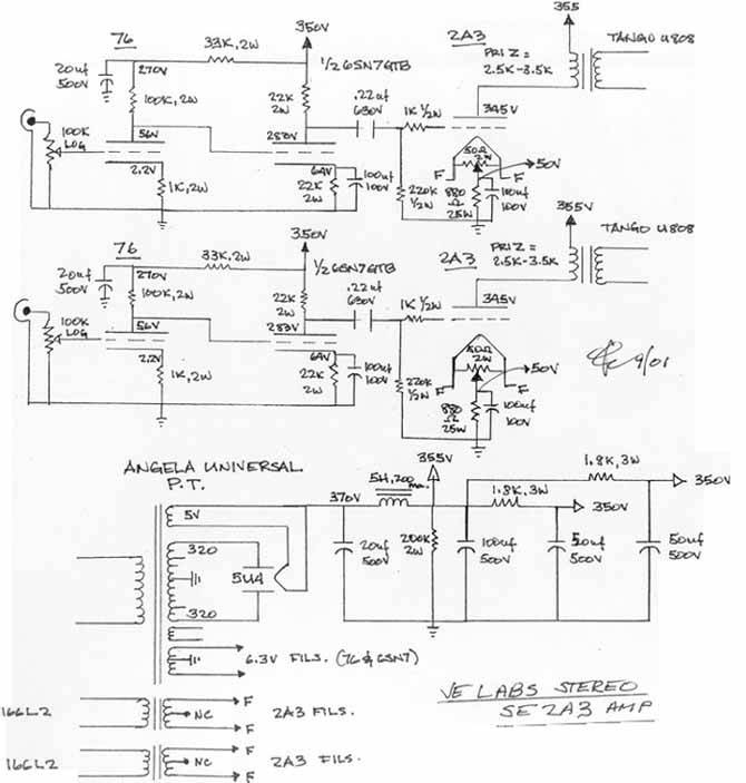
The above circuit shows the power supply as well as both channels
of the stereo amplifier. Instead of the 76 tube, I used one half
of the 6SL7 for the first preamp stage and the other half of the
same 6SL7 for the second stage of the preamp, so the schematic is
the same, it just uses one 6SL7 per channel, and no 76 tubes.
There were several modifications of this basic circuit including
a SRPP (Shunt Regulated Push Pull) version below.
Amplifier Section:
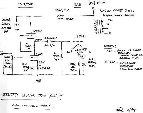
Amplifier
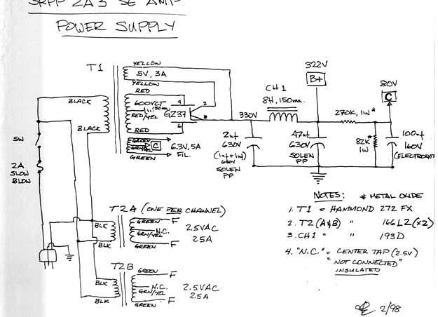
Power Supply Section
Above is the shunt regulated push pull driver stage with
single ended 2A3 output. A similar schematic uses the 6SL7 as a 2
stage driver, I might try it wired both ways.
Here is a longer dissertation of the amplifier theory that I wrote
up:
Go To Tube Amp Theory Page
I found a variety of different amplifiers that homebrew builders
made.
I liked the looks of this amp with the nice wood frame and black
panel.
After deciding on the basic circuit, the SRPP version, I read a
bunch of webpages about various amps and the different brands of
components to use in the construction. Specifically I did Google
searches on the phrases: 2A3 schematic, 2A3 amp, 2A3 amplifier,
and a few others. I decided to use good quality parts but to
try to keep the cost down as much as possible. It appears to me
that the transformers, "iron," are probably the most critical
components, followed by the signal capacitors, so I tried to find
very good parts for those components but still not go crazy with
the cost. Truth be told, I purchased a lot of the parts off of
Ebay, such as the tubes, sockets, some teflon coated silver plated
wire, and a dozen Russian 0.22 uf paper in oil (PIO) capacitors to
use for the signal caps.
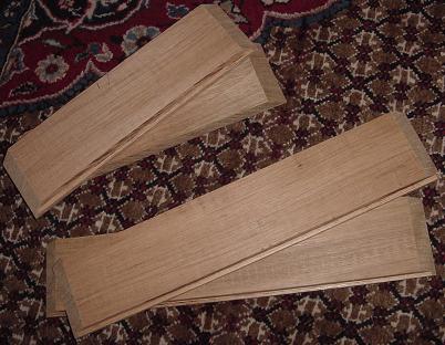
Here are some pieces of the lumber that I got at a local hardwood
specialty store. I was just going to use something like cherry or
walnut, but they had this beautiful piece of wood at the lumber
shop that was called Brazilian cherry, or Jatoba wood. It had a
beautiful color, nice grain, and was as dense as a rock. While I
generally try to make earth friendly purchases and lifestyle
choices, I went against my better moral principles and bought the
piece of wood, feeling guilty all the way home envisioning it
standing in a magnificent tropical rain forest. Anyway, here is
what the pieces looked like after cutting them to the rough
length. Fortunately my neighbor does a lot of woodworking so I
took the pieces down the street and cut the 45 degree angles for
the corners on his compound miter saw, and some grooves for the
panel to set down in to.
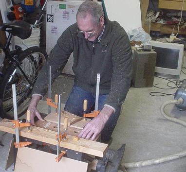
I had to cut out an opening in the back panel for the switch and
electrical connections so I went to work with a router and some
borrowed bits.
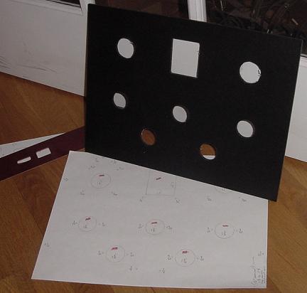
At the same time I was purchasing various components and had the
transformers together so I could make a layout on paper. I wish I
had done the work myself but I took the template to a local
plastics shop and had them cut the large holes and make the panel
up from 3/16 inch thick phenolic XX, may be the Garolite XX
material. That was chosen for its strength and durability. I will
have to drill all the little holes later.
Well that is where I am right now, still putting the frame and
panel together, but am eager to get started on the electrical
construction.
OK, I have put the wood together for the base of the frame and
finished it with spray lacquer. I put the back panel on recessed a
little so it was not so deep in the opening from the back. The
corners are glued with 2 biscuits in each corner to reinforce the
joints, as well as a little wedge of wood glued in for additional
reinforcement and to attach a bottom perforated panel.
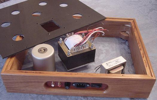
The box is nice and square and very solid. I drilled pilot holes
for all the screws since this wood is so dense. Shown above is the
frame and some of the transformers that will be used.
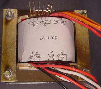
This is a close up of the power transformer. It has two 2.5 V @ 3A
windings for the 2A3 tube filaments, one 5V @ 3A winding for
the rectifier filament, one 6.3V @ 2A winding for the driver tube
filaments, and a 280V- 0-280V @ 150 mA for the plate voltage. It
is a Mars model LM-130D transformer specifically made for this
circuit.
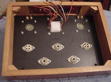
Next, I mounted the transformers and tube sockets on the panel and
attached it to the wood frame. This is what it looked like before
wiring it up. The output transformers are James 6113-HS purchased
from Euphonia Audio. The sockets are vintage ceramic sockets.
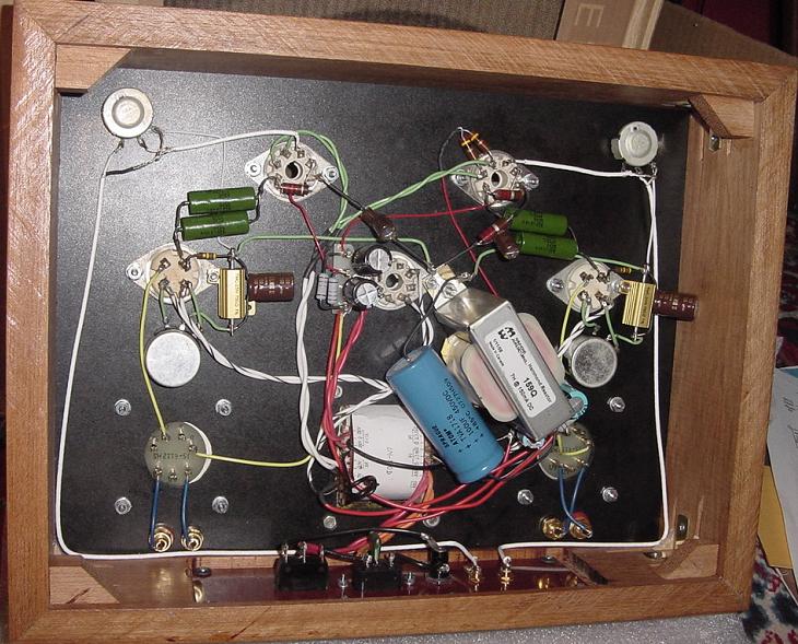
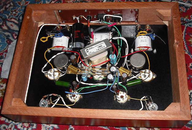
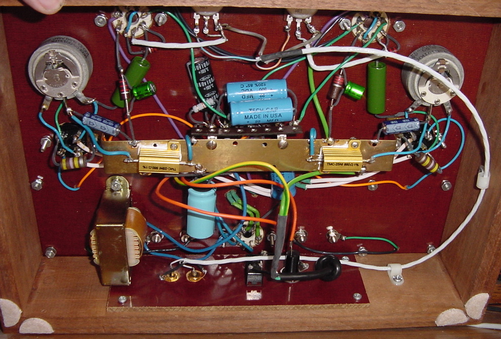
This is the completed chassis showing the wiring underneath. The
green capacitors are the signal caps connecting the drivers to the
power tubes. The pots at the top are the volume controls. The pots
under the 4 pin sockets are the hum balance pots. I fired it up
and checked the voltages and all the voltages were right on the
money according to the schematic, but there was a lot of hum
especially when I touched the volume controls. I then connected a
grounding wire to the housings of the volume control pots and the
hum went away. There is just a barely audible trace of hum with
the volume controls full open and no signal input. My son provided
his iPod for a test run and I hooked it up to a pair of Klipsch
RB-35 speakers and the sound was loud clear and beautiful. No
further adjustments needed. I also listened with a pair of Fostex
single driver speakers I got from Fritz in California, who sells
under Fritzspeakers on Ebay and it sounded even better with a
perfect tonal balance and huge volume.
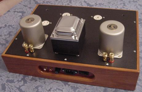
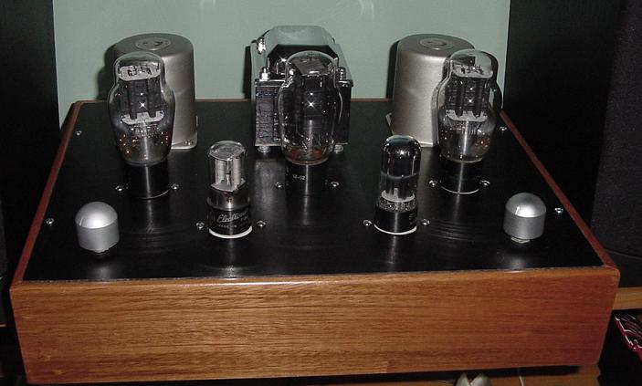
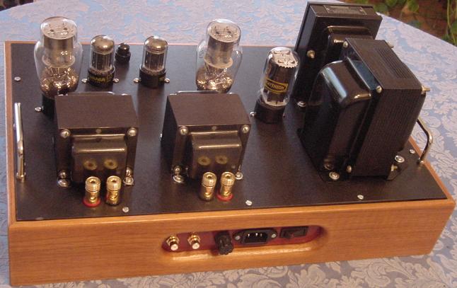
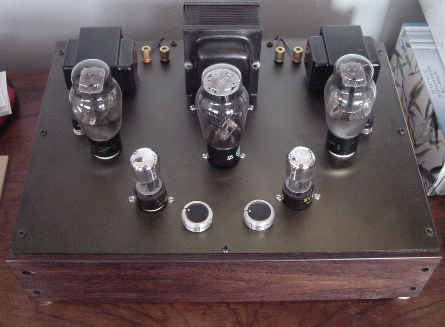
Here is the finished amp. Not a very good photo so will get
another one up soon.
Transformers:
Mars LM-130-D power transformer 120 VAC primary,
Sec 2.5V @ 3A, 2.5V @ 3A, 5V @ 3A, 6.3V @ 2A, 280-0-280V @
150 mA.
The Mars transformers were purchased from VT4C.com in Hong Kong, and
they also had tubes, knobs, wood frames, panels, sockets and
just about everything you might need, unfortunately now out of
business.
James 6113-HS output transformers (also out of
business)
Hammond 159Q choke 7 H @ 150 mA DC, 100 ohms DCR,
500 V test
Tubes:
5U4G rectifier, vintage
6SL7 drivers (can also use 6SU7, or 5691
tubes) vintage
2A3 power output tubes, vintage
Resistors: 2 watt metal oxide for the power supply and carbon composition for the others
Capacitors: Sprague Atom for the power supply filter caps and Elna for the bypasses, Russian paper in oil .22 uf 500V for the signal caps
Tube Sockets: Ceramic body modern made sockets
Fuse Holder: panel mount screw top holder from
Radio Daze
Switch: lighted rocker switch
RCA phono input jacks, gold plated from an
internet dealer in Hong Kong
Speaker binding posts, gold plated from Hong Kong
internet vendor
Wire: various gauges of stranded silver plated
teflon insulated hook up wire 18 GA for filaments, 20 or 22 GA
for others
AC power inlet: generic unit ordered
from Radio Daze
Terminal boards: Four post terminal boards from
Handmade Electronics
Potentiometers:
100K audio taper Clarostat
A-47 half watt
50 ohm hum balance
potentiometers, 4 watt vintage wirewound units
Knobs: Machined solid aluminum
knobs
Wood: Jatoba wood cut to 3/4 inch
thick, and about 3.25 inches width also called Brazilian Cherry
Various hardware 6-32 and 8-32 screws, washers,
nuts, solder lugs
More photos of other amps I have built recently:
This one just finished in October 2009. It uses a vintage power
transformer and vintage single ended Zenith OT-1 audio output
transformers, not audiophile quality but sound pretty good. The
rectifier is a 5Y3G, the preamp/drivers are 12AX7's and the output
tubes are 6V6G's. I found a pair of vintage Zenith 6V6G tall tubes
that give the amp a more classic appearance than the short 6V6GT
style tubes.
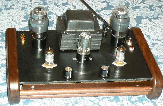
Front view. The power switch is on the right and the RCA input
jacks are on the left.
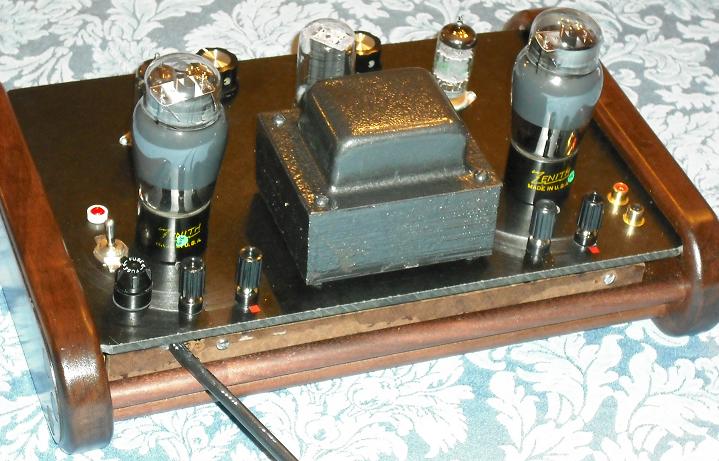
Rear view. The wood is solid walnut with lacquer finish and the 2
end pieces are held together with the 2 walnut dowels.
Below are some photos of a second amp that I
made for a family member. This one used a vintage power
transformer and a vintage 12 H choke that I got from Gary
Schneider. I did need to get a separate 2.5 V filament transformer
for the 2A3's since the old power transformer did not have a 2.5
volt winding. I used a slightly different circuit but same basic
components, it was called the 2001 version of the 2A3 stereo
transformer from Angela Instruments. This one used Transcendar
output transformers and all the "iron" is black. I repainted the
vintage transformers with gloss black Rustoleum paint and it looks
great. The sound is awesome.
I used a big JJ 500 uf at 500 V filter capacitor on this one and
that plus the 12 H choke makes for zero hum and great volume and
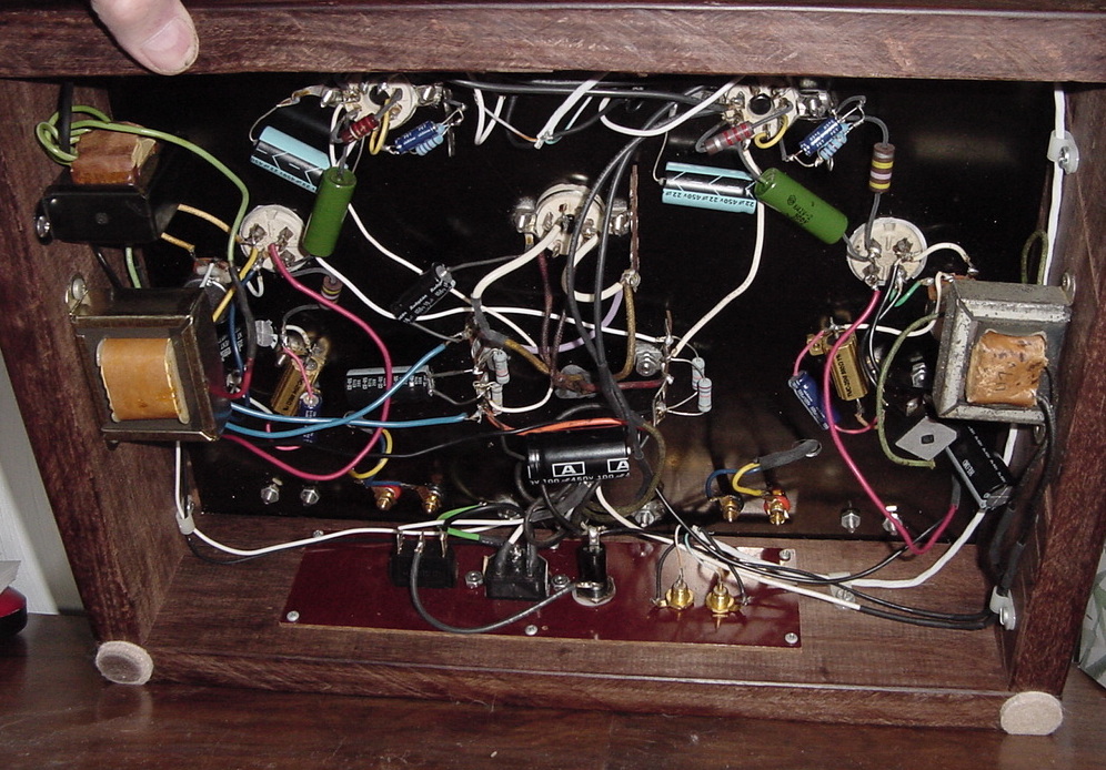
super fidelity with the Fostex speakers. The underneath of the
chassis looks a little messy, but not too crowded as the whole
unit is about 12 x 18 inches overall.
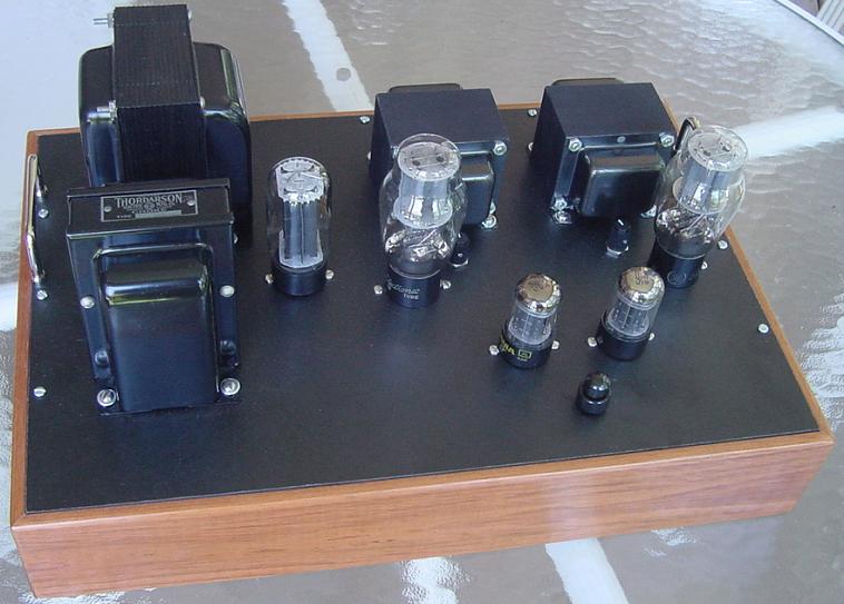
OK, here is one more that I made with transformers from Mars
products, excellent output transformers and the same power
transformer as the first project above.

Top view, flash made some weird light pattern on the panel but
shows the general layout.
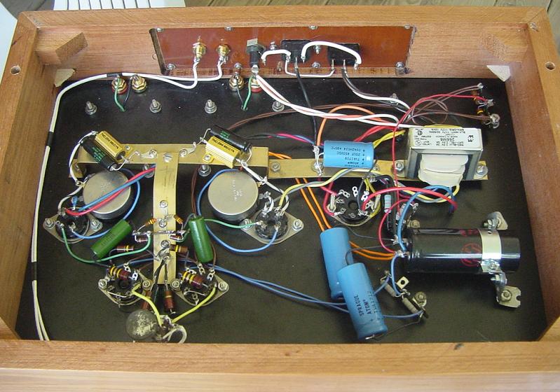
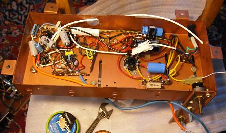
Inside view. It started out neat but got into a bit of a jumble as
things went on. I have a better idea for the ground strip layout
on the next project. I have to use a brass ground bus strip since
the chassis panel is non-conductive and it needs a central
grounding point.
I have made a couple more amps recently and to my dismay found
that most of my favorite companies, especially for transformers
have gone out of business, including the VT4C site that sold the
Mars transformers, James transformers, Transcendar transformers,
and a couple of other Asian sources that used to make single ended
output transformers. Trafomatic Transformers appears to still be
in business, but I can't seem to figure out their web page now.
They made my custom toroidal power transformer for a 2A3
amplifier.
My keeper amps:
These are the last two amps I made and keep for use at home. The
first one uses a toroidal Trafomatic Transformers power
transformer and Transcendar output transformers utilizing the SRPP
2A3 circuit by JE Labs pictured above.
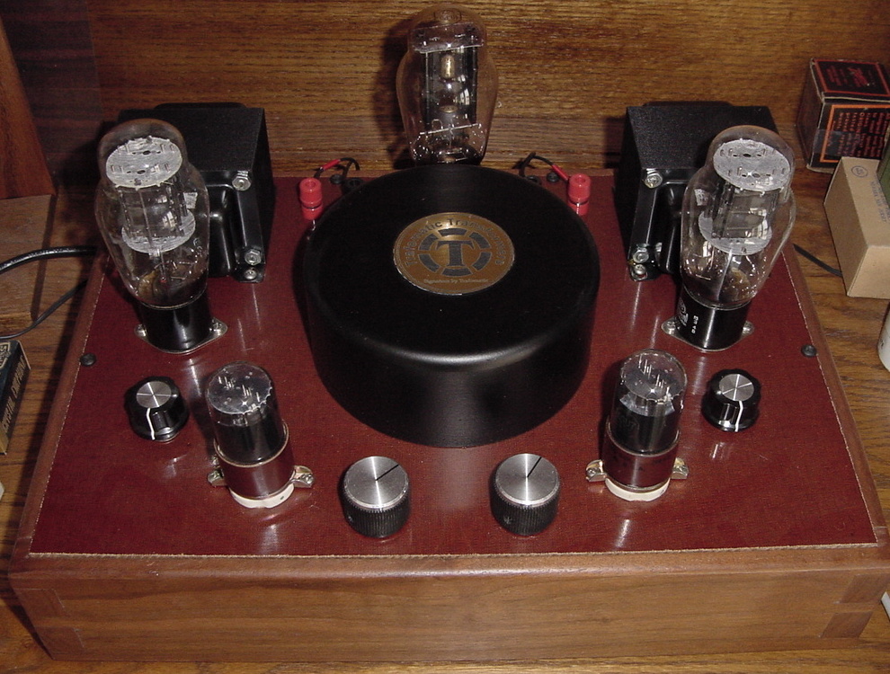
The Trafomatic toroidal power transformer was
custom wound by the company had has 5 separate outputs. A 5 volt
for the rectifier, 6.3 volts for the 6SL7 tubes, high voltage for
the B+, and two 2.5 volt windings one for each 2A3 tube. The
toroid shape supposedly increases efficiency and reduces hum
induced by the magnetic field. The output transformers are
Transcendar TT-010-OT. The hum pots are vintage ceramic wire wound
potentionmeters. The audio capacitors are Russian paper in oil
0.22 uf 600 Volts, silver plated wire for most of the wiring,
silver core shielded audio cable for the feed in, and the rest of
the components are high quality but not over the top resistors,
capacitors, and hardware. The rectifier is a vintage 5U4G, drivers
are vintage 6SL7 (or 6SU7GTY), and power tubes are vintage 2A3.
I made the cabinet from solid walnut with dove
tail joints, finished in clear lacquer with a 3/16" thick phenolic
panel for the top and rear panels. There is a central brass bus
bar for grounding since the panel is non conductive. This amp
sounds great and the hum is absolutely minimal. I am really
impressed with the SRPP circuit by JE Labs having tried half a
dozen different circuits.
6A3 / 6B4G Tube amp


Guitar Amp Project
This is pretty far from what I usually do, but it is my first
attempt to build a vintage looking guitar tube amp for a friend.
Fortunately, I managed to salvage a chassis from an old 1960's
stereo that had good power and output transformers and had similar
tube line up to what I was going to build. I wanted to use a
Fender 5E5 Pro-Amp circuit and make it in a cabinet with the old
tweed and some custom touches. It is still in the works but here
are a couple of photos of the construction.
This is the underside of the chassis after most of the rewiring
and component replacement.
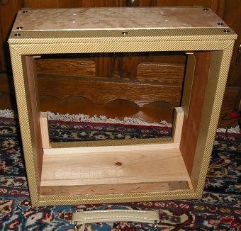
This is the cabinet mostly assembled with the tweed Tolex applied
and the birds eye maple accent panel on the top.
Finally finished the guitar amp. Here are the photos. It works
great with the 12 inch Peavey 6505 guitar speaker.
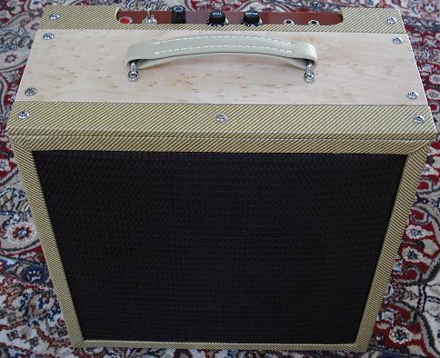
Front view shows grille cloth and matching color handle.
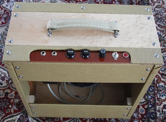
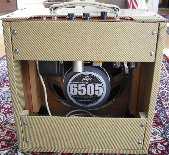
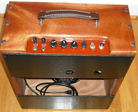
Rear view shows the speaker and you can see the chassis mounted
from the top.
Second Guitar Amp Project
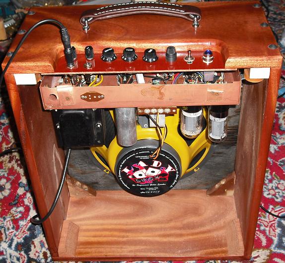
This amp is nearly finished. It uses more or less the same chassis
as the above, with push pull 6L6 output tubes, a 5U4G rectifier,
12AY7 input and 12AX7 driver/phase inverter. It has a 16 ohm
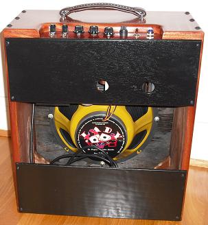
Eminence 12 inch diameter speaker and will shake the walls. I
still have to make some trim parts and the front grille. The
wood is solid mahogany, and is used the same Fender 5E5 Pro Amp
schematic.
Finally finished this guitar amp and had a friend come over and
play it. Sounds great, awesome volume.
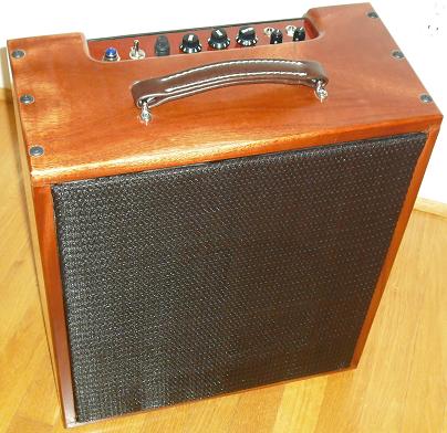
The mahogany finish doesn't show up too well in the photos, but it
looks like fine furniture.
Go To Tube Amp Theory Page