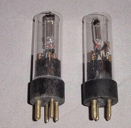
WD-11 Tube
WD-11 Tube
WD-11 tubes were made in the early 1920's for a very limited
number of radios such as the Radiola III and Aeriola Sr or Radiola
Sr. No radios using the WD-11 were made after 1924, so the tubes
rapidly went out of production and are very hard to find or very
expensive nowadays. This page shows a project that I worked on
while housebound during the coronavirus pandemic in March 2020.
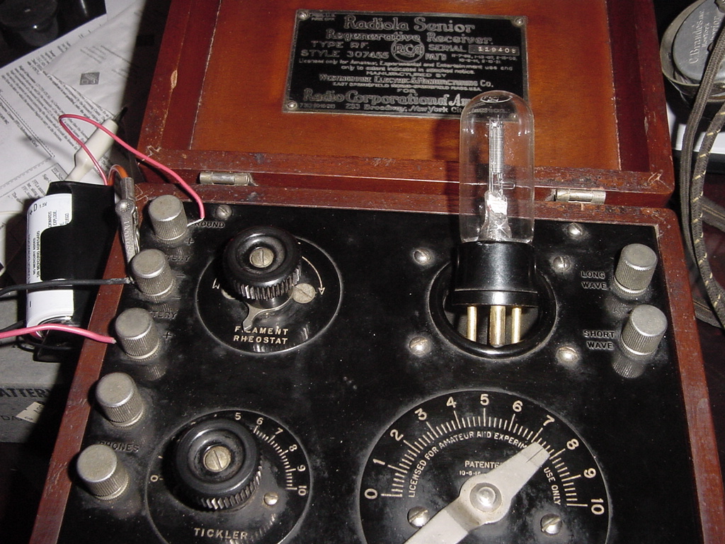
Aeriola Sr. radio showing the WD-11 tube
WD-11 Tube characteristics
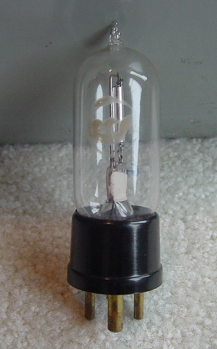
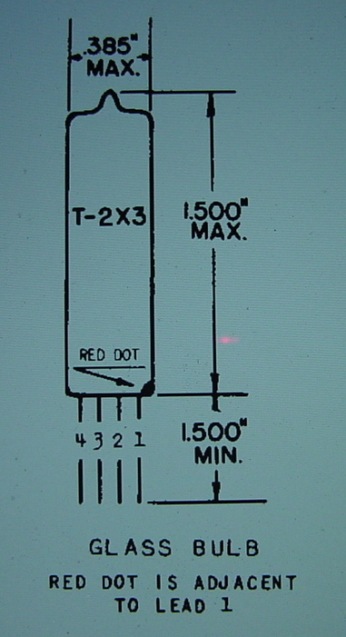
The WD-11 tube had a unique 4 pin tube base
with one big 3/16 inch diameter pin for the plate, adjacent 1/8
inch diameter pins for the filament, and opposite 1/8 inch pin for
the grid. It was a simple directly heated triode, with the
filament being the cathode and operated with 1.1 volts at 0.25
amps for the filament, and maximum plate voltage of 100 volts.
When used in the Aeriola Sr. the B voltage was only 22.5 volts for
detection and regenerative amplification. A detailed blueprint of
the tube base can be found at Radiomuseum.org if you want to see
the measurements of the base layout. They use larger size tubes
and fabricate a base for them. They do look more like real radio
tubes than mine and use tubes like 1A5.. Other tubes such at the
864 can be used as direct substitutes with a base adapter or by
just swapping out that tube's 4 pin base for a real WD-11 base. Radiomuseum
link
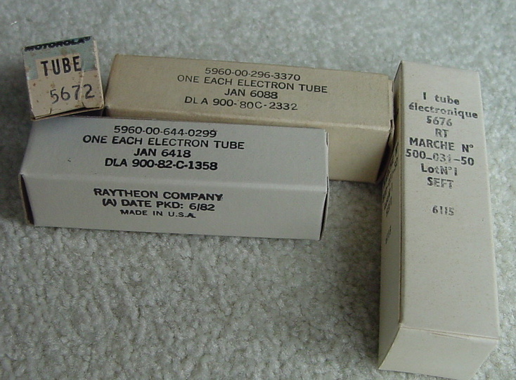
Finding a subminiature substitute
There are several candidates that could be used
in place of the WD-11 and the 5676 submini tube is the closest
match that I would find. It is a triode with a filament voltage of
1.25 volts at 0.120 amps. It can take up to 135 plate volts, and
in circuit gives good results.
Other tubes are the 6418 submini pentode. This
tube used 1.25 filament volts at 0.01 amps, but can only take 22.5
volts max on the plate. I have tested this tube in an Aeriola Sr.
with good results. It would not work for the Radiola III which has
higher B voltage on the amplifier tube. To use this tube you would
tie together leads 1 and 2 (plate and screen grid) to use as the
plate lead. Another possibility is the 5672 pentode, which has
1.25 filament volts at 0.05 amps, and can take 90 volts on the
plate. Again, you would connect leads 1 and 2 for the plate. I
have made up tubes with all 3 of the above and all gave good
listening on my Aeriola Sr.
Filament control
Since all the above tubes have lower filament
current than the WD-11, they need some extra resistance in the
filament control to adjust the output. When using either the 6418
or 5672 tubes, I added a 1/2 watt resistor in series with the
filament leads, ( 27 ohms for the 6418 and 15 ohms for the 5672)
to limit the voltage across the filament to 1.25 volts when using
a 1.5 volt battery, and added a 100 ohm rheostat in the A battery
supply, in order to give you some volume control, so the tube
doesn't come on at full volume and power. (Actually you could use
a 10 ohm resistor for the 6418 and a 2.7 ohm resistor for the 5672
if you followed the precise math for the current, but the slightly
higher resistance would cover for slightly higher battery voltage
and work just fine.)
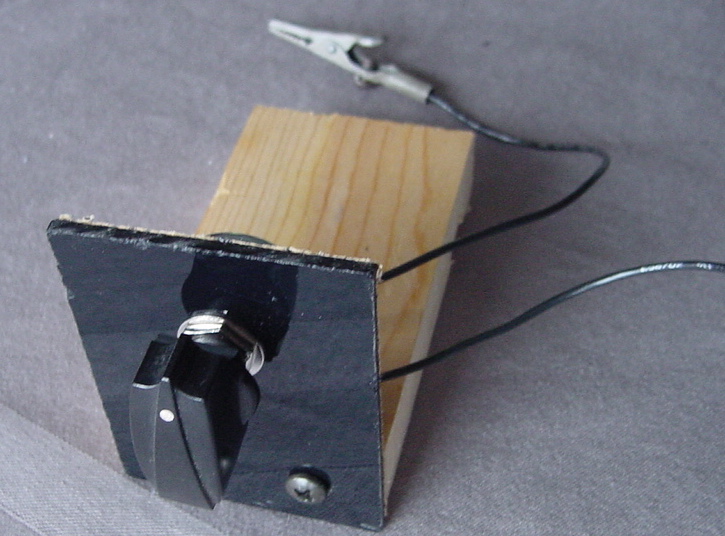
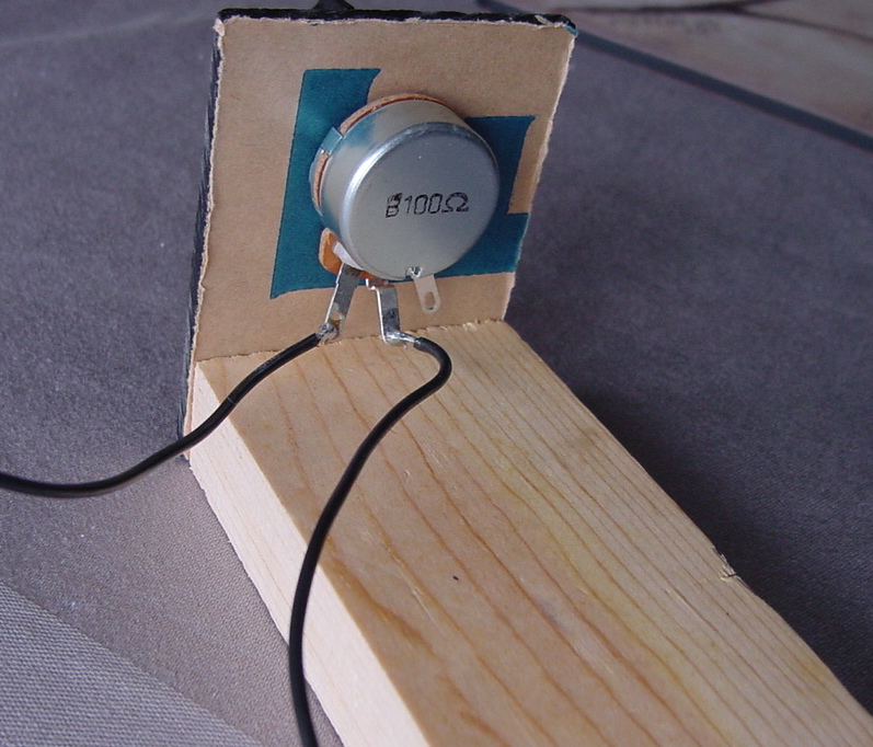
Above shows 100 ohm potentiometer to use as the filament control
rheostat, it is a 5 watt wirewound pot for use with 6418 or 5672
tube.
For the 5676 tube, I added an 8 ohm 1/2 watt resistor in series
with the filament, and that seemed to give a reasonable volume
control just using the stock filament rheostat on the Aeriola Sr.
(The math showed that just a 2 ohm resistor should limit the
filament voltage to 1.25 volts when using a 1.5 volt
battery, but that gave too little volume control using the radio's
rheostat, experimentation showed an 8 ohm resistor gave good
results with the stock Aeriola filament control rheostat and no
external rheostat was needed as it was when using the 6418 or 5672
tubes.)
Construction details
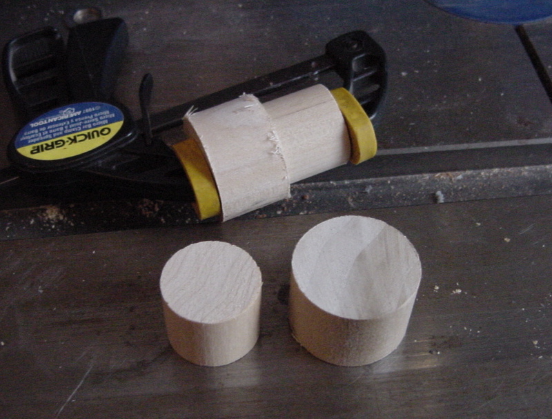
The tube base was made from 2 pieces of wood
dowel, the bottom piece 1 1/8 inch diameter, and the upper piece
7/8 inch diameter. Each piece was about 3/4 inches tall but 1/2
inch would probably have been enough. The 2 pieces were glued
together with wood glue.
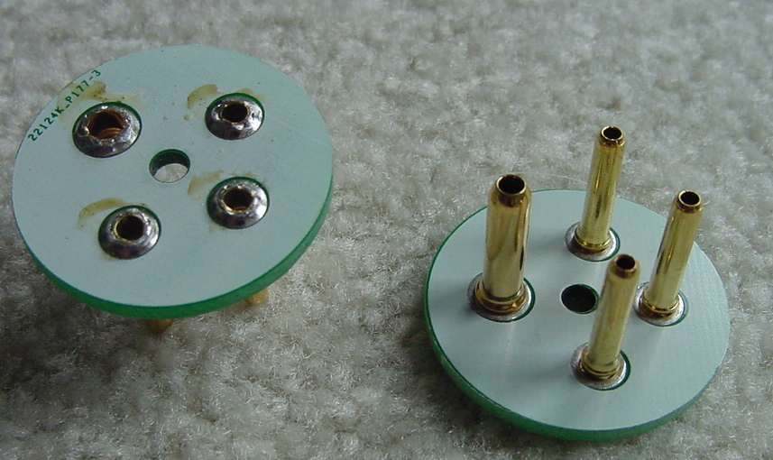
I had ordered some WD-11 tube base wafers from
an Ebay supplier, but found that the pins were too small to fit
snugly in the socket. I unsoldered the pins from one of them and
had a nice template to use to drill the holes for the pins into
the wood base.
The placing of the pins has to be quite exact in order to fit
correctly into the sockets. I screwed the template onto the bottom
of the wood tube base and then used a drill press to drill the
three 1/8 inch and one 3/16 inch holes all the way through the
tube base. The drill press kept the holes straight and square with
the base.
Then I painted the wood black with some spray lacquer.
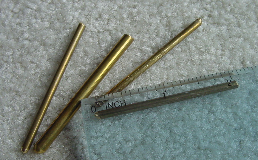
The pins were made from solid brass rods, 18 inch and 3/16 inch
diameter from a hardware store. They ended up being about 2 inches
long and I rounded off the ends with a file.
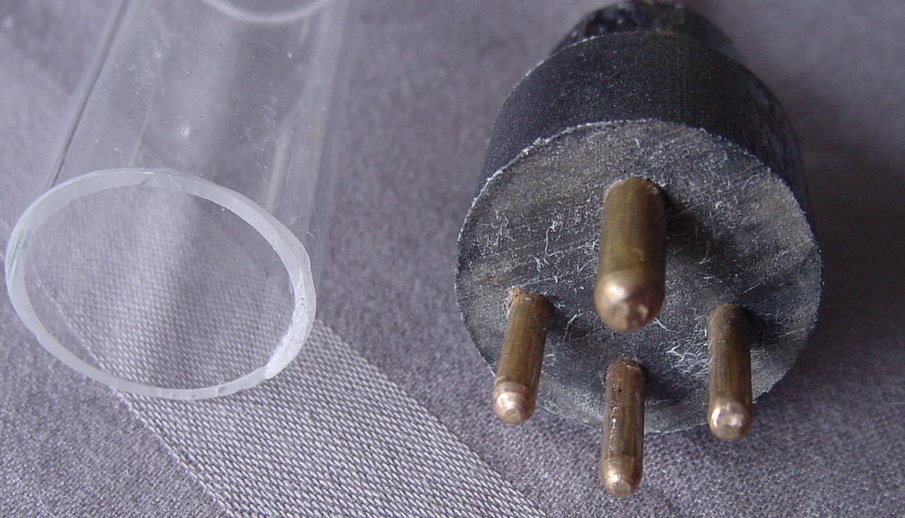
I put a little wood glue into the holes and then tapped them in
place with a little hammer, careful to not split the wood. I used
a real WD-11 tube as a guide to gauge them to the right length out
the bottom of the base. There was about 1/4 inch of pin at the top
to solder the submini tube in place.
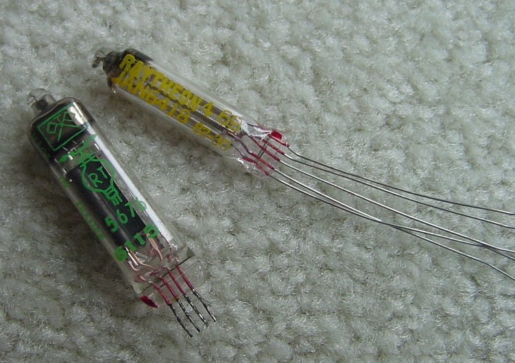
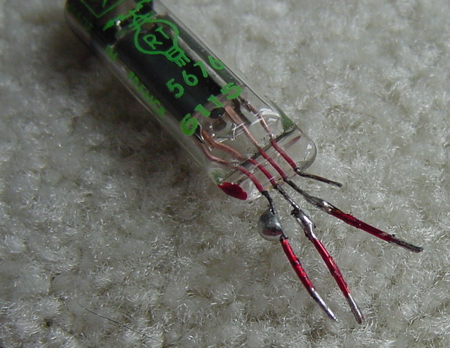
My 5676 tubes came with pretty short leads, so
I soldered on some extensions using enamel covered 24 GA wire. Be
careful not to bend the tiny tube leads as they may break off. I
have seen some for sale with longer leads, might be easier to work
with.
The 6418 and 5672 tubes came with longer more flexible leads and
were easier to work with, I just slipped on a short bit of shrink
tubing for insulation, see below.
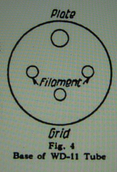
WD-11 pinout viewed from bottom of tube
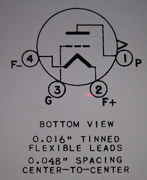
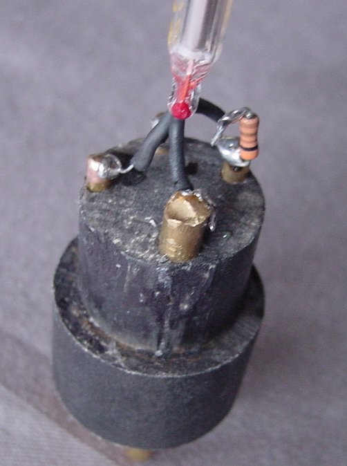
The diagram shows the pin configuration for the
tubes, and the photo shows how the little resistor was soldered
from the brass post up to one of the filament leads. Ignore the
resistor value, it was later changed.
The above was before the little filament resistor was added.
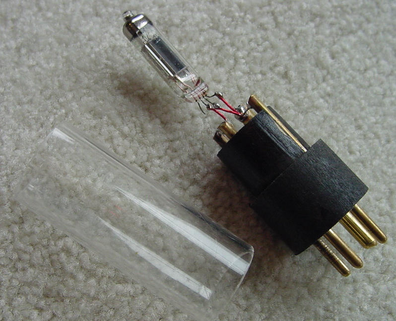
I found some lucite tube that was the right
size to slip over the top of the tube to cover everything up.
The final product doesn't look great, but keeps
you from having to light up a real WD-11 in order to play your
Aeriola Sr. radio. Since the 5676 tube can handle up to 135 volts
on the plate this substitute should be able to be used in a
Radiola III, or IIIA, or any other radio using WD-11 tubes. I will
put up some results here when I manage to do a test in the Radiola
III.