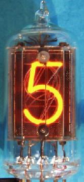
It all started with a trip to a military surplus
warehouse sale where I picked up a bag of dirty used numerical display
tubes, also known as Nixie tubes. They used to be used to display numerical
data on electronic equipment such as frequency counters, multimeters, etc.
before other numerical display technology such as the LED or LCD displays
were developed. The tubes were neon filled light bulbs basically, and the
neon would glow around the cathode wire inside the tube when voltage was
applied to the corresponding pins.
There is now a bit of a resurgence in their popularity for making digital clocks, and there are several rescources online that sell kits and the old Nixie tubes. I got the tubes along with a dishpan full of other electronic parts for $25, so I wanted to make my own clock from scratch rather than build a kit using a ready made printed circuit board. This page displays my project of building a Nixie tube clock.
I did some research on the internet and found quite a variety of dealers selling Nixie tubes as well as kits to make your own clock. Just about all of them used programmable PIC integrated circuits, but I wanted to make mine with just standard logic chips. I came across a project from Europe, see link below to Peter's Nixie Clock Page, and found a schematic for a Nixie clock that uses 4017 decade counter chips along with some switching transistors to drive the Nixie tubes.
I took a look at my Nixie tubes and discovered that
they were 9 pin mini, or Noval, tubes. So I wondered how you could display
10 different numerals using only 9 pins. Turns out that these are Burroughs
B5025 tubes, and were pretty uncommon using a dual anode, or biquinary
circuit. Normally each of the 10 numerals, 0-9, are connected to one pin
for the cathode of each numeral, and there is a single anode (plate equivalent)
for all 10 digits. In my tubes, there are 2 anodes, and each of 5 different
pins were connected to 2 numerals, one even and one odd. Pin 2 is the anode
for all the odd digits, and pin 9 is the anode for all the even digits.

So if you want to display a 1, you would use use
pin 2 as the anode (a1), and pin 8 as the cathode. To display a 0, you
would still use pin 8 as the cathode, and use pin 9 (a2) as the anode.
Therefore, you had to have 2 switching circuits and select both the cathode
and anode for each digit. I finally found a webpage showing a circuit using
ZM1030 dual anode tubes, see link below. However, that clock used a programamble
PIC microcontroller, and I just wanted to use a simple counter. I also
came across Peter's Nixie Clock Page, also linked below, that showed a
circuit using ordinary decade counter CMOS chips and some switching transistors
for the high voltage drivers, but that project used regular 11 pin single
anode Nixie tubes. I emailed the author of that webpage and he very kindly
replied and even drew out a schematic for me to use to use the dual anode
tubes with the decade counter. Here is the partial circuit he sent me,
this is only the driver scheme for one tube.

I took inventory of my parts and have plenty of resistors and capacitors that I use in my radio and audio projects, but this is my first venture in to the realm of semiconductors. The parts I would need for the driver section of the clock would be six 4017 CMOS chips, 20 diodes per tube 1n4148, perfboard, and some transistors, MPSA92 and MPSA 42. I was able to buy all those parts on Ebay for under $20, since they are cheap and commonly used parts. I already had the tubes, tube sockets, and materials to make a nice display cabinet.
Power Supply
Still working on this. I have several choices.
1. Use AC house current with a bridge rectifier to make the anode voltage,
180 VDC. I decided against this in order to keep mains potential out of
the clock.
2. Use a 12 to 15 Volt DC "wall wart" power supply and an oscillator
driven step up transformer and rectifier to make the 180 VDC, and just
use a voltage regulator to utilize the power supply DC current for the
semiconductor circuit.
I had the parts to make this one, and found a schematic
and managed to put it together on an old power supply PCB board from a
discarded computer power supply. Here is a photo of it with a little neon
pilot bulb on it. This board has the oscillator driven by a 555 timer front
and center operating at about 68KHz so I could use a ferrite core and hand
wound transformer you see on the right as the step up transformer. I also
glued the tiny little clock circuit pulse generator you can see at the
left front corner of the board.
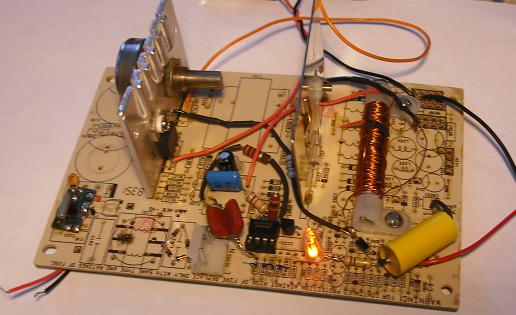
The power supply is plugged in and you can see the
neon pilot lamp lit up to show the high voltage is present.
I had originally used a lower frequency 680 Hz oscillator
and an audio 70 volt line matching transformer which worked prefectly but
the transformer gave off an annoying high pitch hum, so I changed it to
the higher frequency (68KHz) to quite it down and also saves space and
weight as the little ferrite coil is a lot smaller than the line matching
transformer.
3. Use a 12 to 15 Volt AC "wall wart" power supply, and then have an ordinary step up transformer and rectifier to make the 180 VDC, and another rectifier and voltage regulator to make the 12 VDC for the semiconductor circuit.
4. The above power supply was a bit on the large side measuring
about 4 x 6 inches, and I wanted to have a smaller clock, so I hunted for
some other power supply circuits. I came across a "cascade multiplier"
circuit in an old Radio Shack handbook that uses only diodes and capacitors
to increase an AC voltage and put out a higher DC voltage. It works sort
of like series voltage doublers. I needed about 180 volts DC for lighting
up the Nixie tubes, 12 volts DC for the circuitry, and 1.5 volts DC to
run the clock pulse generator. The circuit board pictured below ia a little
less than 2 x 2 inches. It used 8 capacitors and 8 diodes for the 180 volt
DC supple, a 1N4001 Zener diode with a filter capacitor that runs through
a 7812 voltage regulator for the 12 volts DC, and then used a 337 variable
voltage regulator with the corresponding resistors to put out 1.5 volts
to the pulse generator. I had to experiment a lot with the high voltage
to have something small enough, but still get the 180 volts. I couldn't
get enough voltage with my prototype using a 12 VAC wall wart power supply,
and found a 32 Volt AC 500 mA in the drawer.
I found that a cascade of 8 diodes and 8 capacitors gave me 178 volts
DC output when the input was 32 volts AC. The capacitors and diodes needed
to be rated at 2 times the input voltage, and I had a bunch of 1N4148 diodes
that I bought for the driver circuit with voltage rating of 70 volts, and
a bag full of the electrolytic capacitors that are 22 uf at 100 V, and
they seemed to work quite well, and so far, no smoke or fire, and nothing
even got warm with a test load.
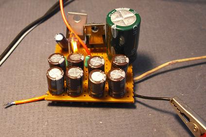
Cascade multiplier voltage supply.
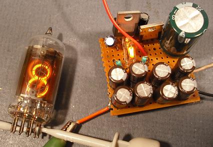
Cascade multiplier powering a nixie tube showing small size about 1.5
x 1.5 inches and puts out 180 VDC, 12 VDC and 1.5 VDC to power the Nixie
tubes, the 4017 IC chips and the timing pulse generator.
Finished Clock
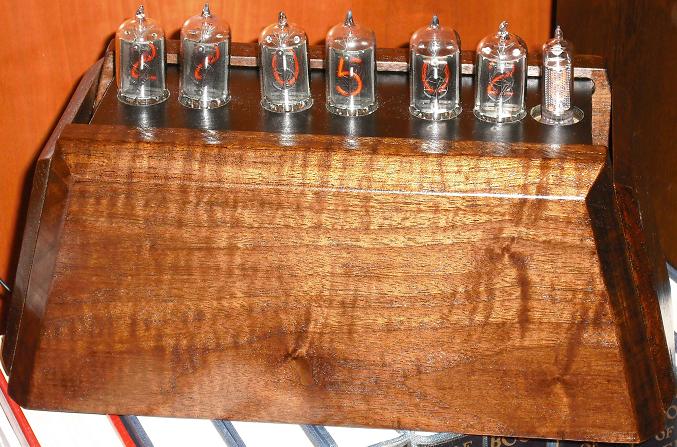
Here is a photo of the clock above, the flash washes out the number
displays, but shows the cabinet. It has display tubes for hours, minutes,
seconds, and tenths of a second. It is fun to watch the tenths fly by.
The cabinet is not as I originally planned it since the chassis was bigger
than I could fit in the original design. The cabinet is made of solid walnut
with beveled edges and a smooth lacquer finish.
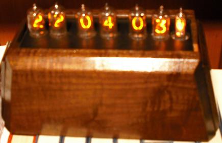
This photo shows the clock without the camera flash so you can see
the digits light up a little better.
Timer
I found quite a few options for the timer circuit. Basically I needed
a 1 Hz pulse generator to drive the first counter and advance the clock
once each second. Some of the circuits used the 60 Hz house current timing
and divided it down to 1 Hz, another used a 555 timer circuit, and still
others used crystal oscillators for the pulse generator. Scrounging around
the house, I found a few old broken analog wall clocks that had been given
out by pharmaceutical reps, the kind that use a 1.5 Volt AA battery and
a regular clock display with hour, minute and second hands. After disassembling
the small drive mechanism and removing the gears, there is a tiny little
circuit board inside that has only 4 connections, 2 to the battery and
2 to a coil of wire that acts as a driver electromagnet for the clock motor.
I hooked up a 1.5 volt battery to the supply terminals, and my little multimeter
to the wires that go to the solenoid coil and found that there was a tiny
pulse of electricity exactly every 1 second, but that the first pulse was
posivite, and the second pulse was negative etc. The pulse duration was
very short with no current flowing during the remainder of the cycle. I
am still working on how to use the alternating + then - pulse to drive
the counter, which needs about a + 0.5 volt signal to trip the counter.
I am pretty sure that it will register the + pulses, and might also register
the - pulses on the upswing side of the pulse. Otherwise I will use a little
bridge rectifier with 1N4148 diodes and hope I don't lose too much voltage
and can still trip the counter with what is left of the pulse after going
through the diodes.
Side Project: LED Pace Clock
In building the Nixie tube clock there was a delay getting the parts,
so I started on a project building a 4 digit timer to be used as a pace
clock for the kids' swim team. A commercial unit costs several hundred
dollars, so I wanted to build a small portable 4 digit pace clock with
numbers big enough to see from a moderate distance. The digital clocks
at the airport use digits about 4 to 6 inches so I thought 4 inch digits
would do. I started with a Radio Shack black plastic project box that is
5 x 7 x 3 inches, and started gathering the rest of the parts and figuring
out a circuit for the timer. It used four 4026B ICs which are decade counters
with 7 segment LED decoding output, that are usually used to drive 7 segment
LCDs, so I needed to use a transistor to get enough current to the LEDs,
which take 20 mA, and the 4026B only puts out about 2 mA, which is enough
to energize a transistor to switch on the current to the LED segment.
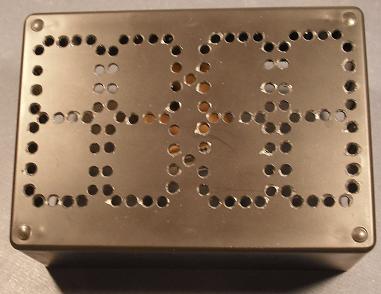
Here is the box with the holes drilled to accept the LEDs.
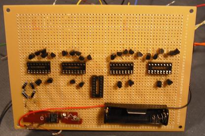
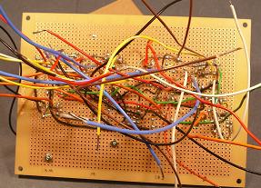
Here is the main circuit board, front and back, at the "wires in the
air" stage. I used a different color of wire for each of the 7 segments
to help with the wiring.
Just finished putting the timer together, and made some adjustments
in the pulse generator circuit, but here is a photo of the finished product.
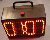
I will put up some more details of the circuit later. It counts seconds
and minutes, ideal for sports timing, like swimming laps etc. It runs on
6 size D batteries, or a 10 volt DC wall wart. When you turn it off and
then back on, it resets to 00:00 and counts up from there. The digits
are about 4 inches tall so you can see it from about 25 yards away.
Nixie Clock Using ZM1030 Tubes This clock used the dual anode biquinary tubes similar to my B5025
Peter's Nixie Clock Page This is a page from Europe showing construction of a Nixie clock using only decade counter chips, no computer programmed software involved. Peter helped me with the dual anode circuit modification, Thanks!
Nixie Resource Link Page This page has links to just about every Nixie page, so I won't list many here, just go to this link and there are dozens listed there