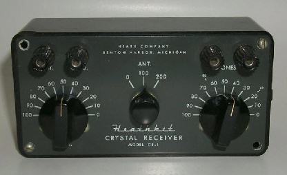
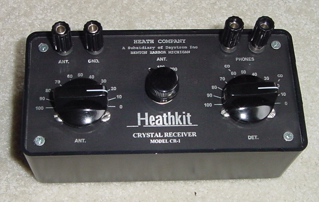
This page gives the circuit and pictoral description of the
famous Heathkit CR-1 crystal radio.
It was a double tuned crystal radio from the
1950's with a series tuned primary that had a 365 pf variable
capacitor and selectable additional capacitance on the center
selector switch. In my opinion, it would have been more logical to
have made the center switch for varying the inductance and using a
tapped primary coil.
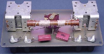
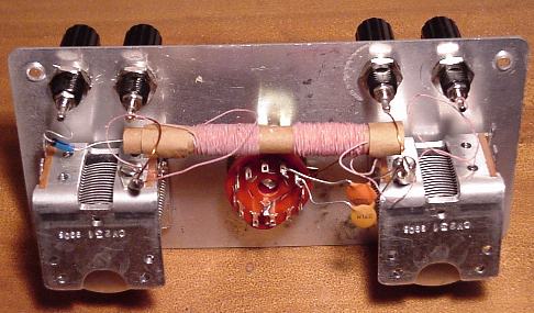
Here is a picture of the inside of the original CR-1.
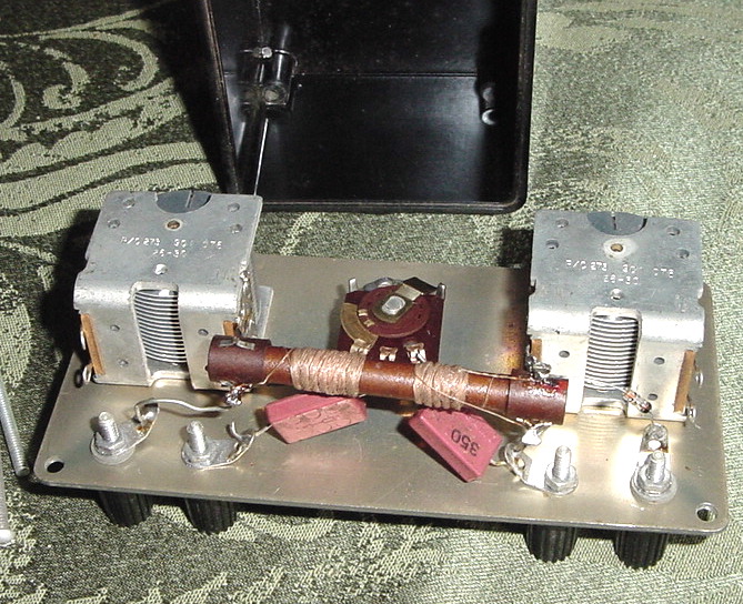
Another photo showing the inside of the original Heathkit CR-1.
Note the rectangular pinkish mica capacitors, the configuration of
the central antenna switch, the "cable knit" appearance of the
coil windings, and the long screws holding the panel to the
threaded stubs that are recessed deep into the cabinet.
Anyway the coils, marked as "transformer" in the diagram, were both wound on a ferrite rod and the secondary coil was part of a tank with the 365 cap and the germanium diode for the detector circuit. They do not give details of the coil construction but with a little experimentation you can get into the BC band tuning range.
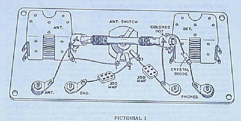
Here is the original circiut:
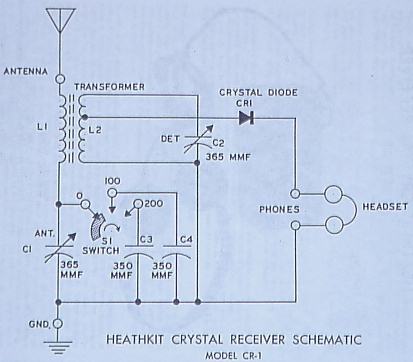
This shows the pictoral diagram of the inside of the set:
First Prototype
In my first building project replica I used a
toroidal core instead of a rod. An Amidon FT 114-61 was my choice
for the core, and 45 turns of 24 GA enamel wire for the secondary
gets the detector tank in the ballpark. (Amidon's webpage is http://www.amidoncorp.com).
I used 30 turns of the same wire would on the same toroid for the
primary with taps at 3, 6, 9 15, 24, and 32 turns. I used the
center selector switch to vary the inductance of the primary
instead of switching in additional capacitors.
The little box is a Radio Shack part #270-1805
that is just about exactly the same size as the original
enclosure. The front panel is made of aluminum, so it serves as a
common ground, but the antenna and one of the headphone binding
posts need to be insulated from it using little fiber washers to
prevent those binding posts from making electrical contact with
the panel.
The radio was originally sold either with or
along side a pair of 4000 ohm Trimm Acme headphones. They were
only middle of the road for sensitivity and a good old pair of
Brandes Superior or Western Electric 509-W's would be much more
sensitive.
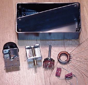
Here is a shot of the main parts on the floor.
The rotary switch, diode, and box are from Radio Shack. The
variable caps were obtained from the Xtal Set Society. The coil is
described above and I got the old mica capacitors from my junk
box. I ended up using a different coil and no padder capacitors
though.
One challenge was to tap a couple of the holes
on the front face of the variable caps to allow them to be mounted
to the front panel using 6-32 screws. Care must be taken to avoid
damaging the capacitor and to keep the metal shavings out of the
ball bearing mechanism.
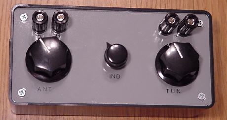
OK, here is the completed CR-1 clone.
This first attempt has the binding posts spaced a bit too close. I
didn't have an original to copy, just pictures. I also tried a
couple of different coil configurations and the one I settled on
has 45 turns of 24 GA wire for the tuned secondary, and the
primary is tapped as noted above.
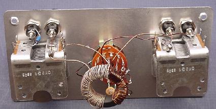
Inside it is pretty simple. Just the 2 variable
caps, the rotary switch wired up to the toroidal coil, and the
diode can be seen from the capacitor to the binding post on the
far left.
I hooked it up and counted 6 local stations in the first minute in
the daytime, and with a good pair of headphones got 7 locals and
another 4 out of state stations on the first night.
If I ever get a hold of an original, I will post a comparison of
the performance.
OK, I got a loan of the original Heathkit CR-1
and here is what I found.
The original CR-1 has a much more definite double tuned effect
than my spinoff. The 2 knobs for tuning the ANT and DET circuits
seem to track pretty closely with each other and both need to be
tuned to the same frequency farily sharply to get reception. It is
easy to miss a station by not having the tuners coordinated. I
found it best to move the DET dial a little then sweep the ANT
knob back and forth a little to zero in on the station if there
was one there.
The circuit gurus emailed me and correctly
predicted that my circuit would pretty much function as a single
tuned circuit. The inductance tap switch mainly varied the
selectivity and I found the 9 turn tap to be good for both
sensitivity and selectivity. There was some noticeable tuning
effect of the ANT variable cap at the high frequency end of the
dial but the DET tuner did most of the tuning. It was,
however, very sensitive and tuned very sharply anyway. In fact the
volume was louder across the entire frequency range than the on
the original CR-1, and I was able to get a couple of weaker
stations that I couldn't reach on the real CR-1. So overall I am
very happy with the performance but I will try another one to try
and clone the coil and performance of the original a little more
closely.
Next Version
After a lot of advice and many coils later, I think I got pretty
close to the original performance. The secret is the coil. I am
told the original has 2 small ferrite cores in it rather than 1
long one so, I experimented with different sizes of cores combined
with different numbers of turns on the coil and then zeroed in on
the correct spacing between the 2 cores. The spacing between the
coils could be measured from outside but the stuff inside the
cardboard tube was impossible to discover without damaging the
coil. It looks like the core is about 1/4 inch diameter and
extends just to the outer edges of the coil windings when you look
into the ends of the tube. If anyone knows the exact original
specifications please let me know. Anyway, I was able to pick up
the same stations with this version as with the original.
After many attempts and examination of an
original coil and X-ray here is what I ended up with. I used
21/44 Litz wire for the windings. The antenna coil was about 140
turns with a 9/16 inch slug inside that part for about 335 uH
inductance. The space between the coils was 10 mm or about 7/16
inch. The detector coil had about 90 turns with a 9/16 inch long
slug inside that and measured 240 uH. On some of the coils, I
tried bringing out a tap about 30 turns from the stator end of the
winding for the detector tap. Hard to say if this made and
noticeable difference, not much if any. This coil seemed to
duplicate the performance of the original in both sensitivity and
selectivity. Any closer spacing of the coils and you get too much
coupling and the tuning gets very broad.
Here is a front label that I made on some thin acetate plastic,
printed the Heathkit logo on it, and glued on to the front of the
aluminum panel. I sold a few of these clearly presented as home
made clones, though I have occasionally seen my radios show up for
sale on Ebay advertised as a genuine Heathkit, which should be
obvious that they are not. Note the short flat Phillips head
screws, the lettering which is clearly different than the
original, and the coil inside is clearly hand wound as opposed to
the tidy machine winding of the originals. Also note the round
modern ceramic chip capacitors and the multiposition switch. If
you run across one of my radios being passes off as an original,
you can refer the seller to this page, but the radio itself,
unless damaged, should work just as well as the real thing, and
there were only a dozen or so ever made, so they are quite rare
indeed!
Addendum 5/29/01
Unravelling the secrets of the CR-1 coil, or The CR-1 coil Exposed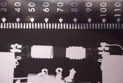
This is an actual X-ray of a Heathkit CR-1 coil. As you see, it
has the 2 coils each with its own separate ferrite slug. The best
I can measure, each slug is about 13 mm or about 1/2 inch long by
1/4 inch diameter. The separation between the slugs is 7/16 inch.
It looks like the slug in the larger (antenna) coil is not quite
centered under the coil. I am not sure if this was intentional or
not. Anyway it was helpful to know how it was made so one might
get a better idea of how to make a duplicate.
The Amidon R61-025-400 core can be cut into the 1/2
inch lengths for use in constructing a coil like this one. I will
post further information as I progress with this project. Thanks
Mike!
Link
to Miller Tuner Page (Just
replaced this link, hope it is working now) This is a link
to a page with more information about another famous crystal
radio, the Miller 565 / 595 Tuner. This was my next project. The
modified schematic is shown below.
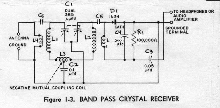
Parts List:
Part Description Source, Part#
C1 2 gang 365 pf tuning capacitor from Xtal Set Society
C2 0.1 uf capacitor Mouser 5989-250V.1
C3 0.05 uf capacitor Mouser 5989-250V.047
C4 200 pf capacitor Mouser 140-50P2-201K
C5 10 pf capacitor Mouser 140-50N2-100J
C6 15 pf capacitor Mouser 140-50N2-150J
R1 100K ohm resistor Mouser 293-100K
L1 Tuning coil 1 Core from Amidon FT 82-61, see text below for
winding
L2 Tuning coil 2 Core from Amidon FT 82-61, see text below for
winding
L3 Negative mutual coupling coil, see text below for construction
L4 270 uH peaking coil Mouser 43LR274
L5 (marked L in schematic) 2500 uH RF choke
Mouser 542-70F253
D1 1N34A Germaniun Diode
Miscellaneous hardware:
Perforated Circuit Board Radio Shack 276-1396A
Solder Tabs Mouser 534-7312
Machine Screws 6-32
Washers size 6
Tuning Knob or Dial
Cabinet Radio Shack part #270-1807
Wire for the coils and hookup
Binding posts or Fahnstock clips
The secret of this set is in the construction of the coils.
L1 and L2 are straight ferrite rods wound with
Litz wire. The best reproduction of this was to use an Amidon 2
inch by 1/4 inch diameter ferrite rod of material 61, and wind on
85 turns of Litz wire. I had some 21 strand by 44 GA wire and this
worked well. I actually measured the inductance of the finished
coils and adjusted the windings to get them exactly the same, to
the uH, about 250 uH.
L3 is the real secret of this set. After
trying several different core forms for this, the best seemed to
be a ¼ inch hardwood dowel about 2 inches long. Wind 2 strands of
the 30 GA wire onto the form together, side by side, close wound
for somewhere between 20 and 31 turns and secure. Take the left
end of strand A and the right end of strand B and join them
together for the bypass to the grounded capacitor. The remaining
free ends go to the points indicated on the circuit.
I am told you can get the actual flyer from the Miller Company.
This circuit and the construction details are published in the
Newsletter of the Xtal Set Society in a 2 part article starting in
Jan 2002. You can see the construction details and alignment
instructions there.
Back
to Scott's Crystal Radios