Baseboard, any piece of wood that the components will fit on, roughly 6 x 8 inches
Coil form, 2 inch diameter by 6 inch long cardboard tube coil form
Wire, about 50 ft of 26 GA enamel insulated copper wire
Diode, germanium diode, such as 1N34A or 1N60
4 Fahnstock clips and mounting screws
365 pf variable tuning capacitor, with knob and mounting screws
Construction Directions:
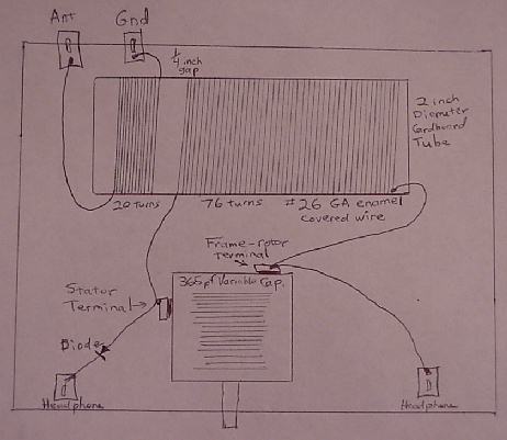
Coil: Wind about 20 turns of the wire onto one end of the coil form close spaced one layer thick neatly wrapped, secure the ends by poking 2 holes through the tube with a safety pin and thread the wire in one hole and out the other to secure it in place, leaving about 6 inches free on each end. Leave a 1/4 inch gap and wind on another 76 turns of wire in the same direction, securing the ends as before and leaving about 6 inches free for making connections.
Attach the 4 clips to the baseboard, and mount the variable capacitor on the baseboard, being careful not to put the screws too far into the frame or they will damage the tuning plates.
Scrape the insulation off the ends of the wire and attach the top end of the 20 turn coil to the ANT clip and the bottom end of the 20 turn coil to the GND clip.
Attach the top end of the 76 turn coil to the stator terminal of the variable capacitor and the bottom end to the frame or rotor terminal of the variable capacitor.
Attach the diode from the stator terminal of the variable capacitor to one of the headphone clips, and attach a wire from the frame terminal of the variable capacitor to the other headhone clip.
Be careful not to get the diode hot or it will melt the internal junction.
Connect antenna and ground wires to the ANT and GND clips. Attach 2000 ohm headphones to the headphone clips. Tune stations with the variable capacitor tuner.
You can experiment and vary the number of turns of wire and the spacing to zero in on the coverage of the AM broadcasting band, but these values should get you in the ballpark.
A good ground is essential, and should be a short run to a grounding rod in moist soil. Don’t use your household electrical system ground. A long antenna is best but even a 12 foot indoor wire should pick up local stations.
If it doesn’t work, double check all the connections, check the function of the headphones with a
AA battery, check or replace the diode, scrape and tighten or resolder the wire connections. For a simpler circuit, only wind on the single coil of 76 turns and attach the antenna to the top end of the coil and the ground to the bottom end. This will work OK but won't be as selective as the 2 circuit setup.