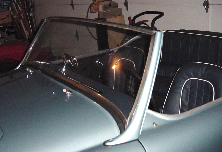
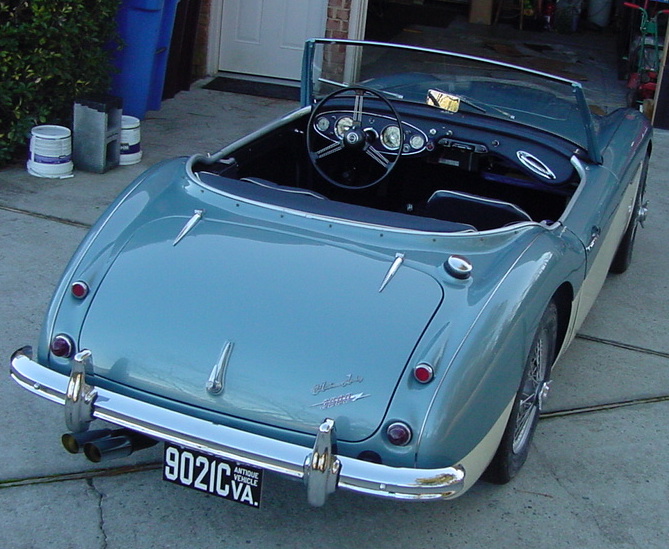
Assembling Blue 1960 Austin Healey 3000 BT7
Finally got the body back from the paint shop
after about 2 years, but the paint job is excellent. Now to
start the assembly process. This is a chronological record of
the reassembly. Over the 2 years that the body was in the shop
getting the finish body work and paint, I rebuilt the main
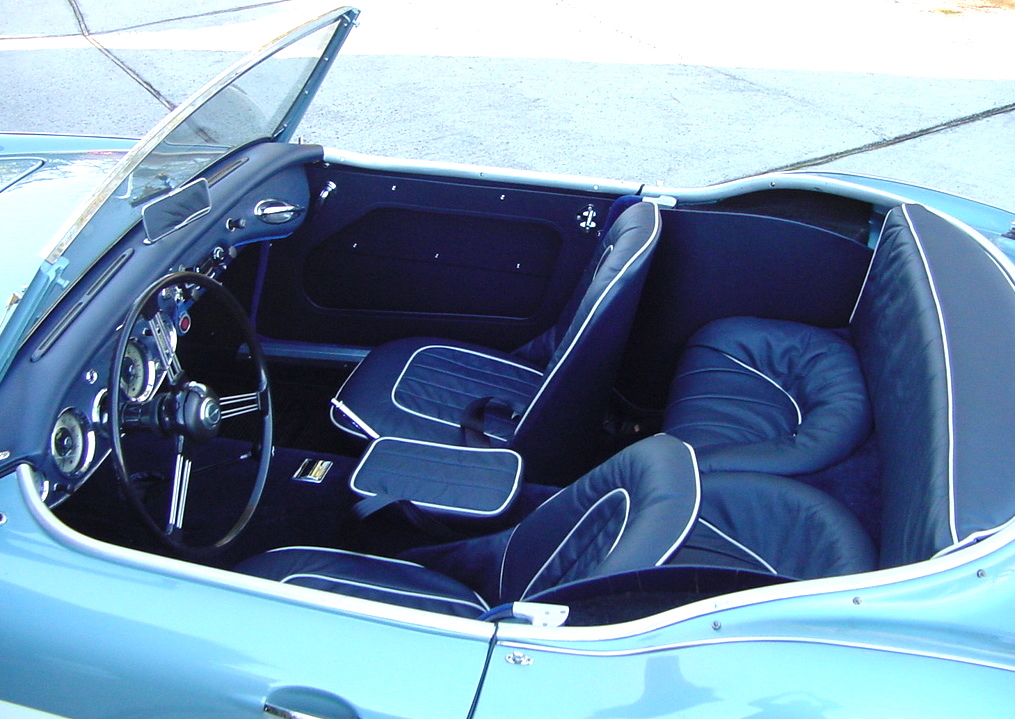
components and assembled various subunits, so the seats are all
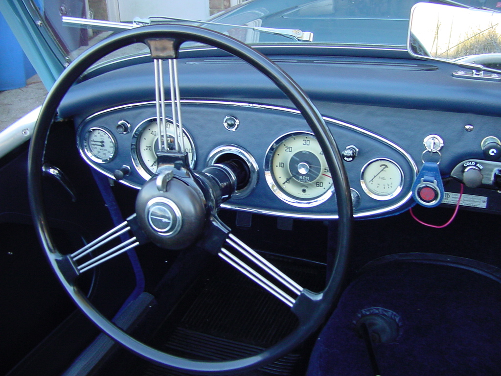
upholstered, and the dashboard is done with all the instruments
installed, so mainly the job is to put it all together. After
restoring the red Austin Healey, my wife thought I had gone
totally crazy to buy another basket case junker, but this one
appeared to have "good bones" and I succumbed to the temptation
and did it again. It sat in the garage for a couple of years,
then another year or so to disassemble everything. The frame was
good, the rocker panels and rear door pillars were rusted out,
as were some of the floor panels and lower parts of the fenders,
and footwell panels. It had been in a barn for many years and
all the wiring was shot, and the upholstery was rotted. The
engine, gearbox and overdrive needed complete rebuilds, as did
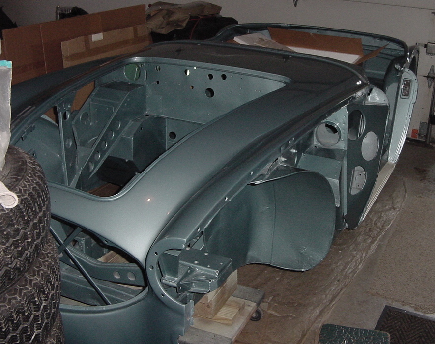
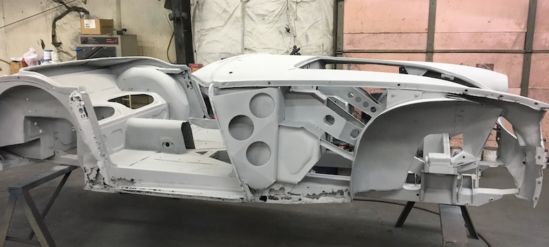
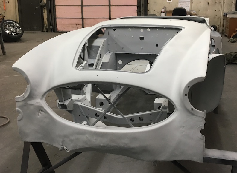
every other component. As you can see it was stripped down to
the frame, and one shop did a sandblasting job, and I managed to
replace some of the body components such as the footwell panels,
rocker panels, door pillars, and patched up some wheel well
rust. The body shop did the rest where it needed to look good
and welded on the fender repair panels from Moss Motors, and
straightened out some dents in the aluminum shroud, which they
actually removed from the frame for better access to get
everything primed and painted.
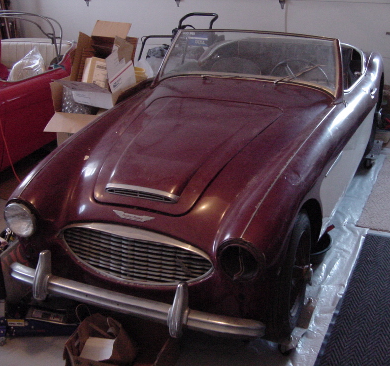
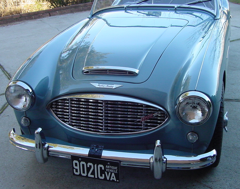
Here are a few "Before" pictures of the car as I got it.
Original color was Old English White, but someone had added the
2 tone maroon paint.
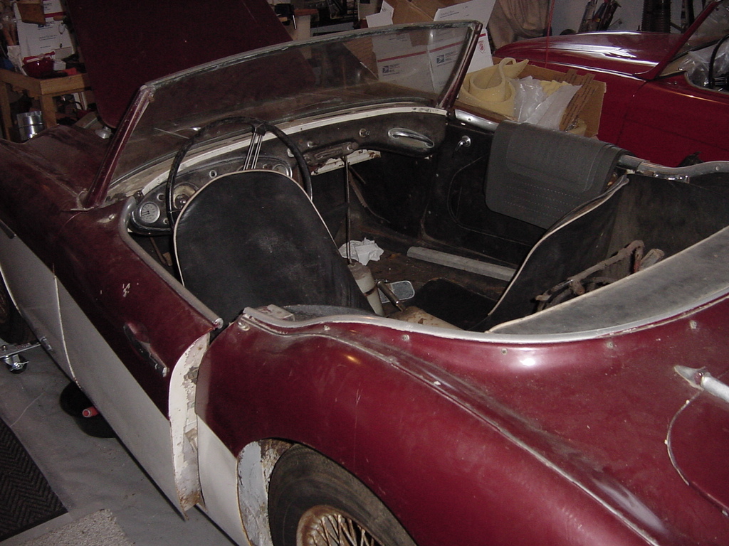
The upholstery was completely rotted as were rocker panels and
lower fender sections.
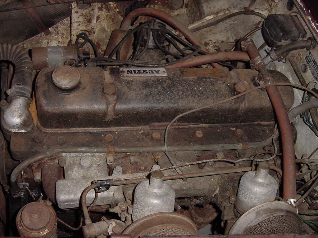
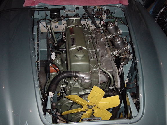
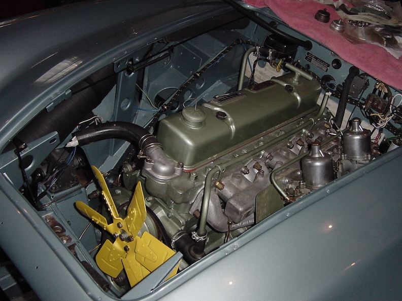
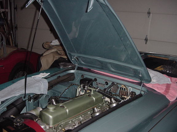
The engine compartment was quite grungy but the engine wasn't
seized. Still did a full rebuild anyway. Above photo was taken
after removing a lot of mouse nest mess and a few dead
mice.
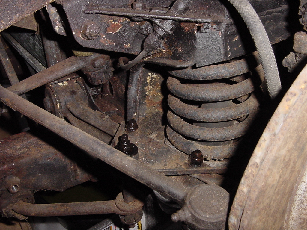
Everything underneath was black with greasy grunge. A lot of
stuck nuts and bolts to undo. Tear down and parts cleaning and
rehab took a year or so, and below is only the reassembly
process.
Some photos of the chassis at the sandblasting shop, they
sprayed on primer as well.
Obvious bad spots were the rocker panels, door pillars, inner
and outer sills, all of which were cut out and new ones welded
in.
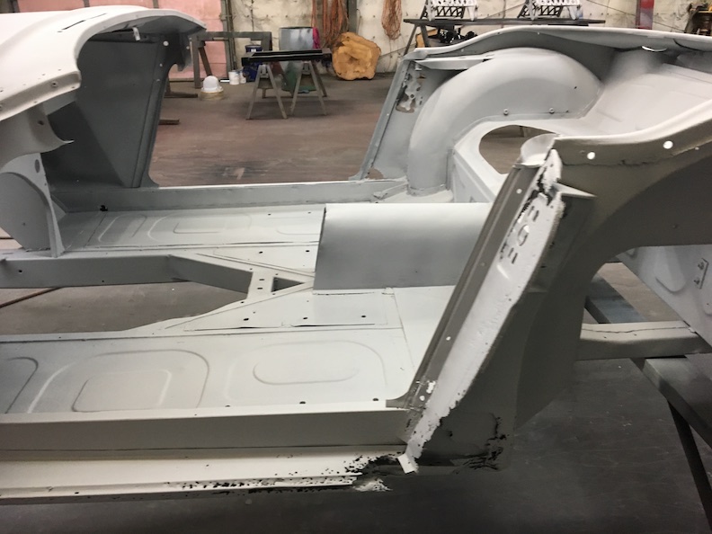
Floor panels and main frame were in surpisingly good shape,
unlike the door pillars and sills.
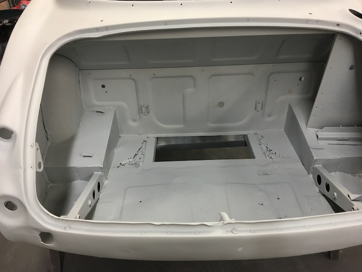
Back end needed some new sheet metal under the fuel tank.
Front end needed a fair amount of work on the shroud.
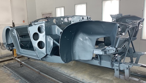
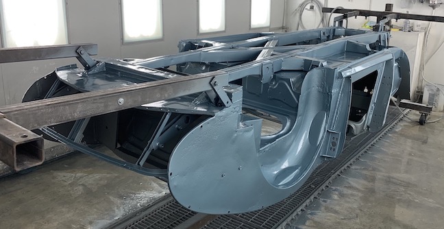
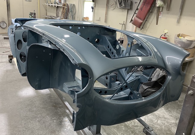
Here are a few photos from the shop where they did the paint job
and finish body work.
Week 1
Doors:
I got the doors back before the main body, so
I started putting those back together. The hinges were already
attached and painted body color. There is a strip of upholstery
vinyl glued (contact cement) on the inside of the door near the
upper edge to fill in the gap between the aluminum trim molding
and the inner door panel.
Door latch assembly. Next I installed the
door latch assembly, the long connecting rod and the inside
control unit, called the remote control in the Moss catalog.
Those parts had been cleaned up and lubricated so they work
smoothly. The outside door handles were installed along with the
gasket and the little rubber buffer. checking that they were
installed on the correct side so the lever engages the latch
mechanism when you pull the door handle.
Check straps: Attached the check straps using
the chromed screws, plain and lock washers, careful to get them
right side up and on the correct side. I taped them down with
some masking tape so they don't bang around and chip the paint.
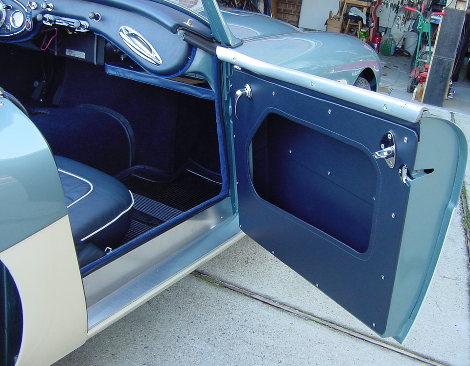
Door Panels: The three panels inside the door
cavity go in next, the little bottom one goes in first and the
other 2 are held in by 3 trim screws. The ones I got had some
lines impressed into them but I had to pretty much break them
along the lines to get them to bend to 90 degrees. I marked the
position of the wood strip on the sides of the door frame to use
for positioning the screws, and drilled a tiny pilot hole 3/32"
and screwed them in place. The third little trim went in first
and just lays in the bottom once it is bent along its length.
Once all that is on, I put on the main door panel. I had to
drill pilot holes through the panel and the metal, since you
can't really locate the original holes in the metal through the
panel. I used the old panel as a ballpark template for where to
put the screws.
Door Hardware: The inside door handles were
kind of a pain to install, as it was hard to push down the inner
ring of the escutcheon in order to place the pin through the
shaft. It was easier after trimming the panel backing around
where you push that piece down, just be careful to avoid cutting
outside of the diameter of the larger escutcheon ring. The side
curtain attachment plate goes on with 3 screws, some used sheet
metal type screws like mine, and some used machine screws with
nuts and washers. I prepunched some holes through the panel
where these screws go through. The lower screw tends to hit the
door latch mechanism, so I ground that one short enough to avoid
hitting it but long enough to grip the panel metal.
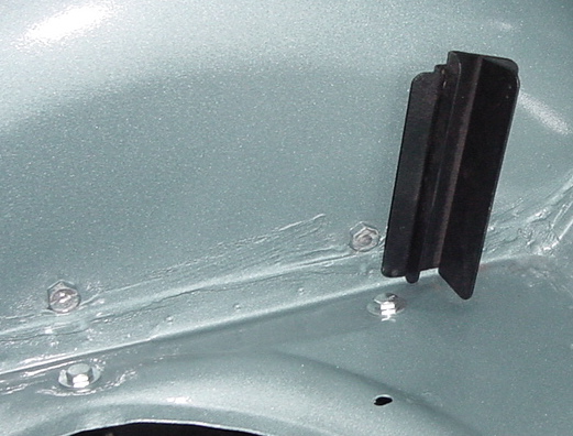
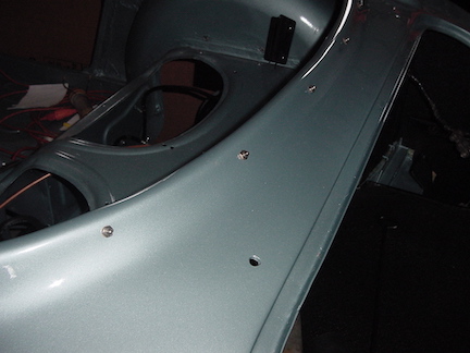
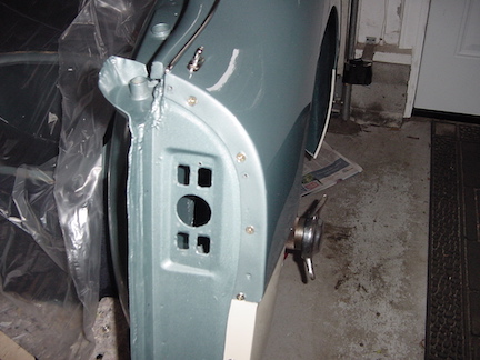
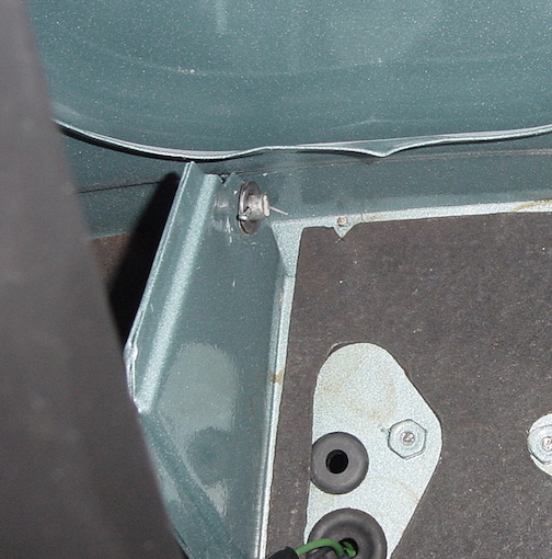
Front Fenders: The only thing I did at this stage is to install
the chrome trim flash using the 3 nuts with plain and lock
washers since you can't get to those once the fender is
installed. Make sure they are installed pointing the right way,
see photo. 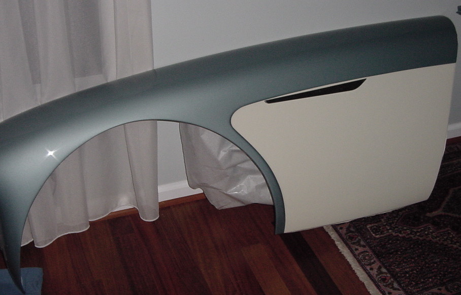
Body: Since paint gummed up most of the threaded bolt holes on
the frame and body, I spent a couple of hours running a thread
chaser through all the holes so the bolts will engage properly
without getting jammed up. There are a lot of them and it took
most of an afternoon.
Firewall tar paper: Glued on the firewall tar paper using
contact cement. Lots of wires and stuff go through the holes so
you can't put it on later.
Heat Shields: I got a new set of heat shields and attached them
with the screws and big washers supplied in the kit.
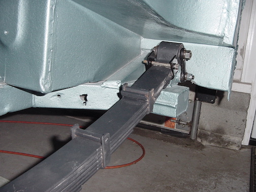
Rear leaf springs: No particular reason for putting the rear
leaf springs on at this point, but it didn't seem like they
would get in the way of anything else and they were taking up
space in the house so on they went. The springs had been
sandblasted primed and painted and I had new bushings and new
rear link pins. I used Nylock nuts on the rear link pins in
addition to the lock washers. The grease nipples on the rear
supports had been painted over by the body shop so I cleaned
those up and shot some grease through to make sure they would
pass the grease through. I also bolted on the buffers with the
rubber pads on to the upper surface of the main frame members. I
also greased up the front bushings since there didn't appear to
be any grease fittings on them for later use. It was a tight fit
putting the bushings into the loops at the end of the springs,
and I used a big socket and a hammer to pound them in place so
as to avoid hitting the bushing itself.
Gave up on the timed weekly updated, so will just update as I go
along.
Boot Area: Armacord etc. The black boot (trunk) liner comes
as rough cut pieces that you need to trim to fit. I used some
giant magnets to hold the pieces in position them marked and
trimmed them with a sharp utility knife. They are best to install
in a certain order to have the bound edges overlap on top of the
cut edges. I will show the order I used:
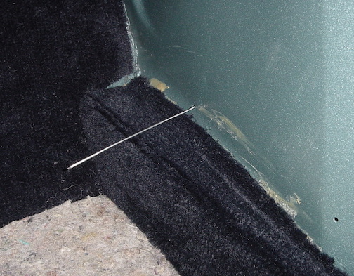
TIP; Put some masking tape over the screw holes so you don't
gum them up with glue, and don't glue down the edges where you
need to install the fender screws or other items. Glue those areas
later. After gluing a piece down let it dry then push a pin
through the places where you need to cut a little hole for screw
holes for the wood tire blocks and battery block. Use a utility
knife to cut holes where the battery and tire block screws pass
through.
1. First the piece over the curved part of the left wheel
well, cut and glue in using carpet glue.
2. Second is the flat piece in front of the battery. Glue in
place.
3. Third is big piece on the front wall. Hard to trim and needs
holes cut for the gas tank strap anchors. Glue in place so the
bound edge on the left side covers any gap over the the left
fender well piece. There are also 6 rivets holding this piece,
locate the holes by pushing a pin through and using that spot to
push the rivet in place. Don't glue the corner where the wiring
harness comes through the wall.
4,5. Next are the 2 side pieces of the flat fender walls, trim and
glue in place so the bound edges cover any gaps, tape over screw
holes first, and don't glue down the spots where the fender screws
go through until after those screws are in place.
6. The next piece is the rear piece behind the gas tank, trim and
just lay in place.
7,8 There are 2 smaller side pieces to trim and just lay in place.
9. Last is the big piece that covers the gas tank, but haven't
installed it yet.
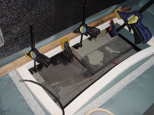
Gas tank Gasket: The foam gas tank gasket needs to be glued in to
keep it in place. I used some clamps to hold it while the glue
dried.
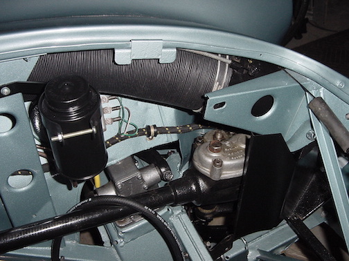
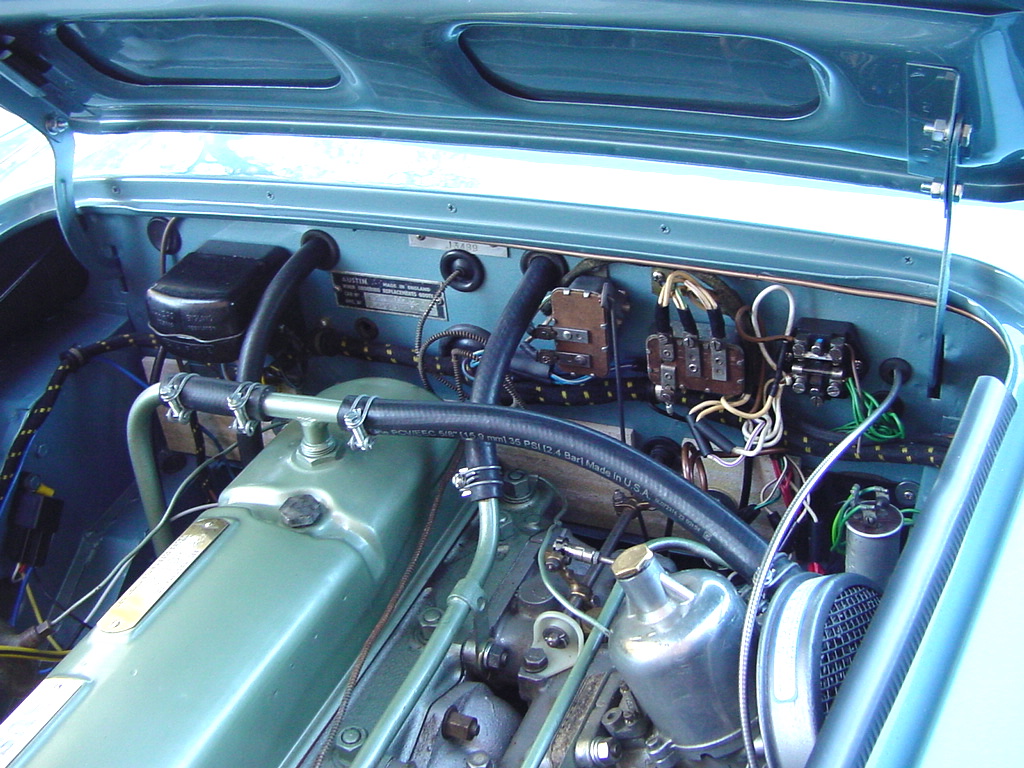
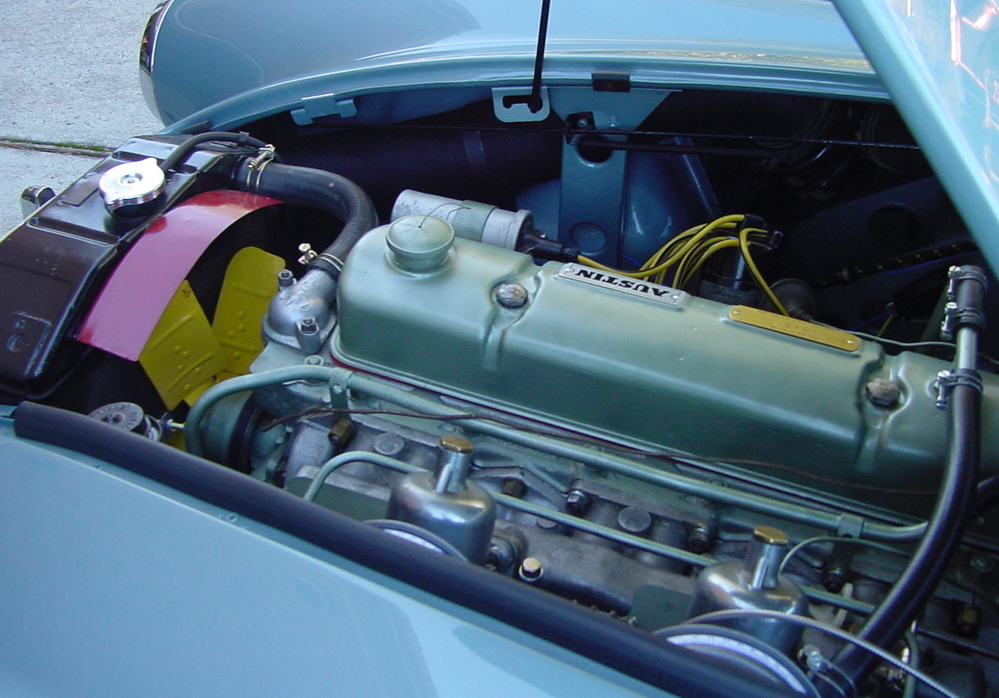
Engine Compartment Components: Lots of electrical components here
to screw onto the firewall. I did my best to test the components
that I reused, and installed them. Also put on the accelerator
shaft and the rear bolts on that were hard to get to, used a small
box end wrench and connected the little rod to the throttle
position switch.
Wiring Harness: Before installing the harness, I tried to mark the
wires with tape to show what they connected to, referring to the
wiring diagram.My harness was not exactly the right one and had
some push on terminals where I needed bullet type, so I had to cut
off the push terminals and solder on the bullets where needed. I
was able to reuse the overdrive harness.
Note: I think I should have installed the oil pressure gauge pipe
before all the wiring as it was difficult to get in later.
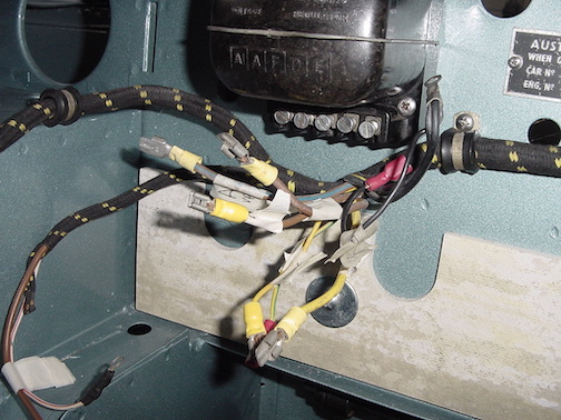
Firewall all wired up and accelerator shaft in place.
Horns: The original horn circuit has hot wires going to the horns
and back up the steering column and the horn button then completes
the circuit to ground, so a lot of current is flowing through the
horn button. In spite of trying to keep the car as original as
possible I made a few concessions to improve functionality and
installed a relay so the only current that flows through the horn
button is what is needed to trigger the relay, and the relay then
completes the circuit and the horn sound is much clearer. I used
the same kind of relays for the headlights, so the only current
through the light switch is the trigger for the relay.
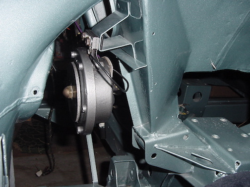
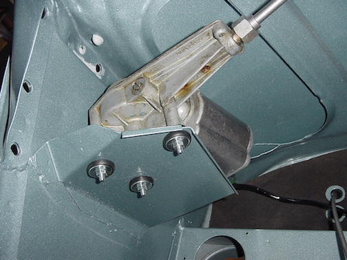
Wiper Motor: Installed the wiper motor on its bracket. The new
bushing kit was impossible to push the grommets through the holes,
so I ended up cutting them and putting the 2 halves in one on each
side so you can't see they were cut. I connected the wires before
mounting the motor as they were hard to reach after mounting.
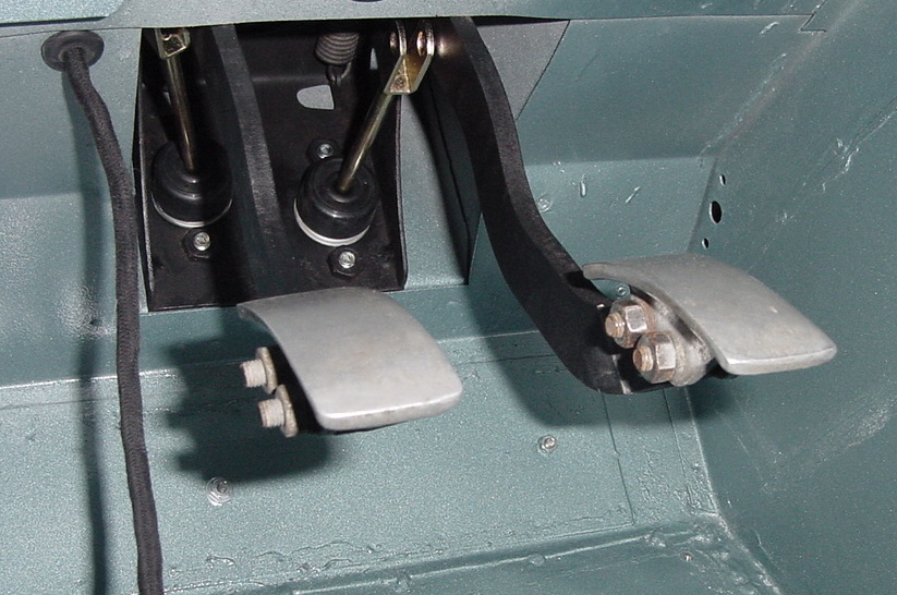
Brake Pedal Box: I installed the brake/clutch pedal box with the
6 bolts without the master cylinders just to get it positioned and
firmly in place. Then I removed the 2 bolts that would hold the
brake master cylinder and inserted that master cylinder and
screwed down those bolts. Then I removed the bolts for the clutch
master cylinder and inserted that one and screwed it down. This
was much easier than trying to hold the box in place with just the
2 upper bolts holding it. Attached the plungers to the pedal arms
with the clevis pins. That part was done lying on my back looking
up at the plungers in order to see what I was doing when inserting
the clevis pins and cotter pins.
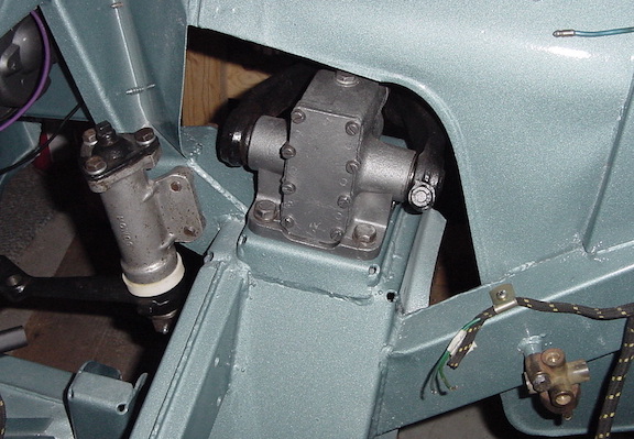
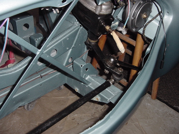
Steering Idler, Front Shocks, Brake 5 way block: I
installed the little front shock absorber buffers and then the
front shock absorbers, just bolt them onto the shock platform.
Then attached the steering idler using the 3 big bolts and the
alloy spacer. Installed a new brake switch on the 5 way block and
attached that onto its post.
Splash Guards: These attach with 4 sheet metal screws, though I
had to upsize the screws to get them to hold. There is a bracket
to attach to the front lower edge, but the other end of it will
attach later when the front grille is installed. Don't put these
on until after you install the horns or you can't get to them very
easily.
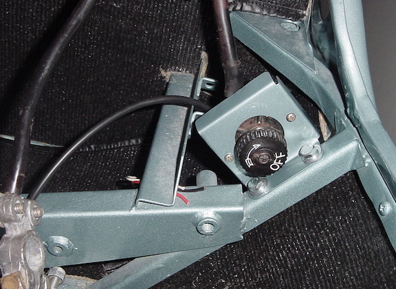
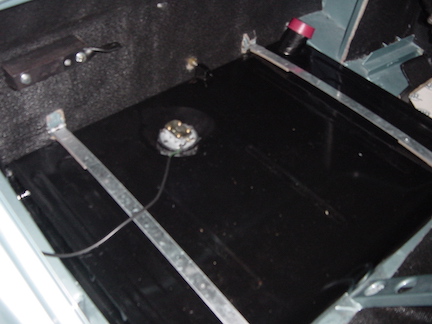
Battery Switch: This was attached to its bracket in the boot. I
used some White-Out correction fluid to re-ink the writing on it.
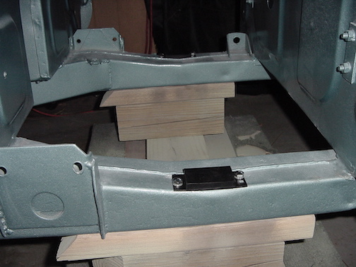
Rear Axle Differential: Had a friend here today to help with the
heavy rear end installation. TIP: Might even need 3 people to do
this or 2 big strong guys. Install the bump stop boxes AFTER the
rear end, and maybe even the fuel pump so those don't get in the
way. Basically we just wiggled it in place and tipped the front of
the differential up about 45 degrees to get it started, but
smashed a finger when it set down on the frame member. I used a
heavy wire after it was in place to keep the front from tipping
down due to the weight and had it resting on the frame buffers.
Will need to put the jack under the leaf springs to get them to
mate up with the axle. Put the fiber pad in place and then the big
U bolts and plate underneath. Had to unbolt the rear shocks from
the frame to get the shock links inserted through the spaces on
the axle, but forgot to put those "distance pieces" in place so
had to do that job again with those in place.
Haven't bolted it in place yet, or attached any of the parts yet,
waiting to get the fiber pads from Moss Motors.
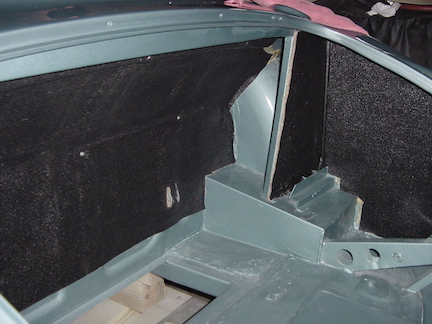
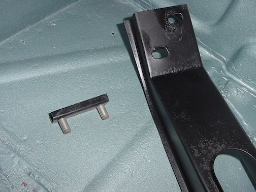
Rear Seat Bracket: This bolts on through the rear fender wall to
hold the rear seat and the rear quarter panel in place. I had to
trim off the bolts from the bump stop box to get clearance for the
quarter panel to tuck under the bracket.
Bump Stop Box: Put this on after installing the differential.
Uses four 1/4 inch bolts. The new boxes didn't fit properly as
they were and I had to use a grinder to cut the channel for the
body seam, and even then had to file the screw holes to line up
with the holes in the fender well wall.

Gas Tank: The foam support for the gas tank was a bit too thick
and the outlet for the fuel couldn't clear the hole in the wall,
so I had to slice off about half an inch of height to get the tank
outlet to go through the hole. I installed the 2 metal straps
using the clevis pins and the nits and big D shaped washers in the
back where they go through the floor of the boot. TIP: Screw on
the section metal fuel line before strapping down the tank, and
remember the rubber grommet where the fuel line goes through. The
wire for the fuel sender is screwed onto the post. Then you can
cover it all up with the Armacord trunk liner.
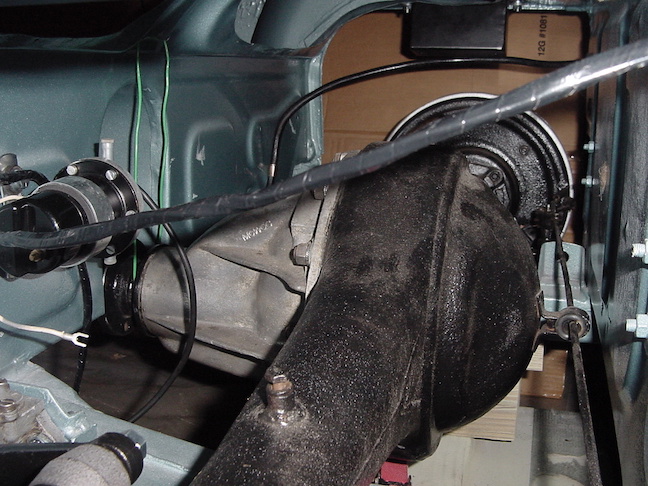
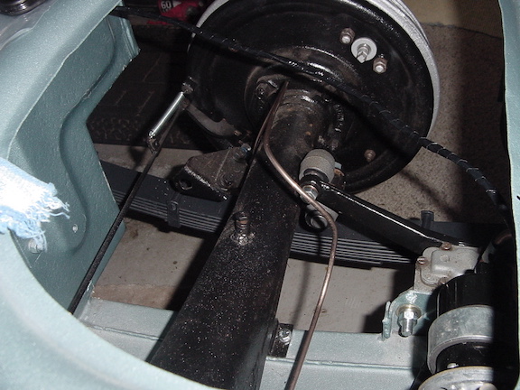
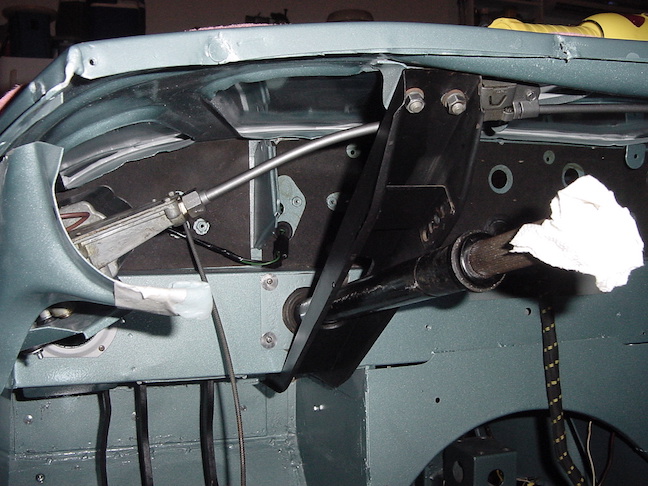
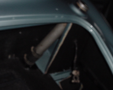
Rear Axle Stuff: The hydraulic brake lines and handbrake need to
be connected to their places The photo shows the left side with
the new brake pipe bent to fit. It goes up over the top of the
differential and there is one clip at the top of the diff that is
held by the top screw in the differential housing. This clip has a
larger mounting hole that fits the housing screw. The left rear
brake pipe attaches to the 3 way union which in mounted on a
little extension bracket on the right side of the axle housing.
The flexible hose attaches to the front hole of the 3 way union,
take care to put in the copper washer here as the washer
compression forms the seal. The front end of the flexible hose
goes through the hole in the bracket on the heelboard, and the
main front to rear pipe connects to that.
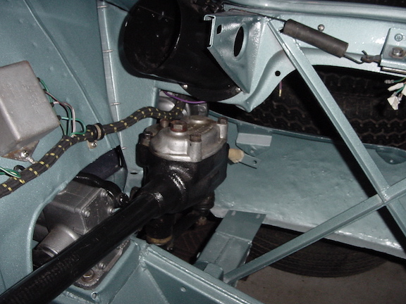
Steering Column, box and Support: This will be installed using
the little bracket that holds the 2 bolts from turning that goes
inside the air duct so the bolts go down through the holes. TIP:
Put the little 2 bolt bracket in place first, then put the
steering box and column in place, then wiggle the column support
bracket over the column and bolt everything in place. Make sure to
put the alloy spacer in place where the bolts attach the steering
box, and make sure you have put the blanking place, grommet and
felt washer onto the column before inserting it in place. I had to
adjust the position of the firewall heat shield a bit to allow the
blanking place to go into its place.
I stuffed some paper towel into the hole in the steering column to
keep me from banging my head on it when working in the
cockpit.
Brake Pipes: I started to install the brake pipes, even though I
haven't attached the front suspension yet. I still had the old
pipes and used them as templates for bending the new pipes into
shape to fit, since they were purchased in coiled form. I started
with the ones on the rear axle, then the flexible hose from rear
axle to frame, then the long front to rear pipe which used several
of the clips to hold in place, then the front left and right
pipes. Already out a new brake light switch on the 5 way
union. Be careful when screwing the pipes into the unions as they
are easy to crossthread.
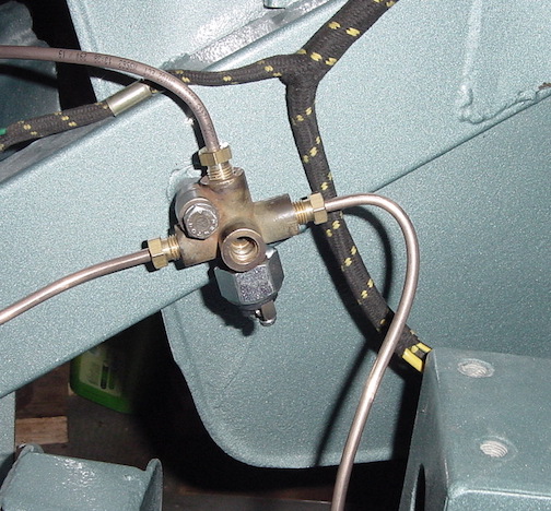
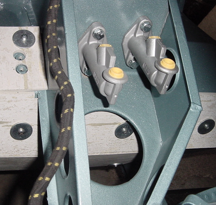
Brake Fluid Tank: The tank for the brake and clutch fluid is
mounted on a bracket as shown, and the pipes running to the master
cylinders. It is important to get the ends of the pipe lined up
for a good fit to avoid leaks, so some extra time getting them
bent just right will pay off.
Steering rods: Now that the steering box and idler are in place,
I installed the cross rod. Remember is you need to adjust the
length that one side is left hand thread.
Handbrake: Didn't really need to put this in place just yet, but
wanted to get the brakes done and can work around it when
installing the cockpit stuff.
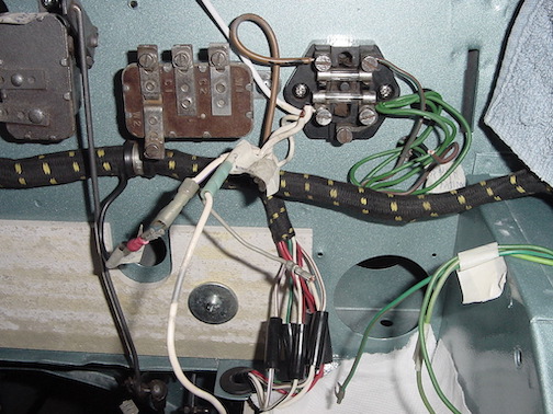
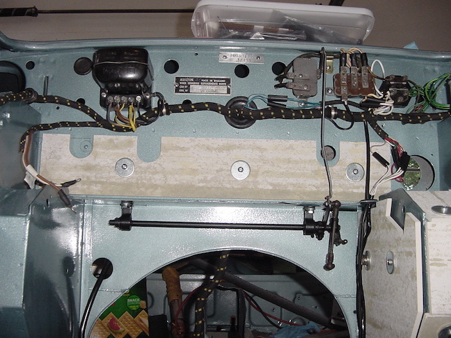
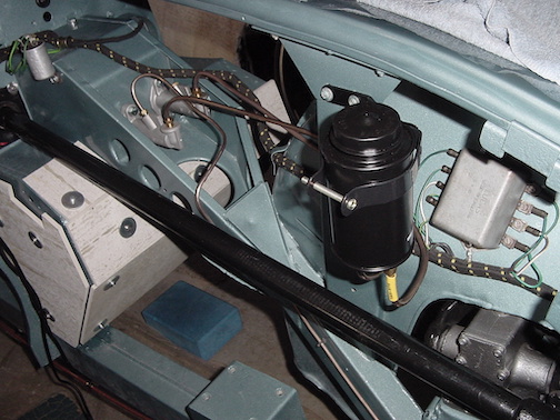
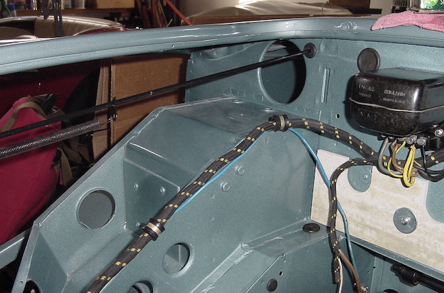
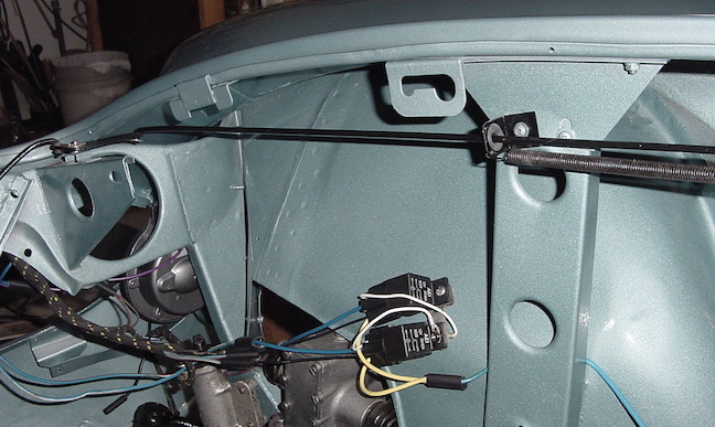
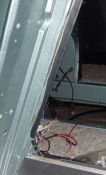
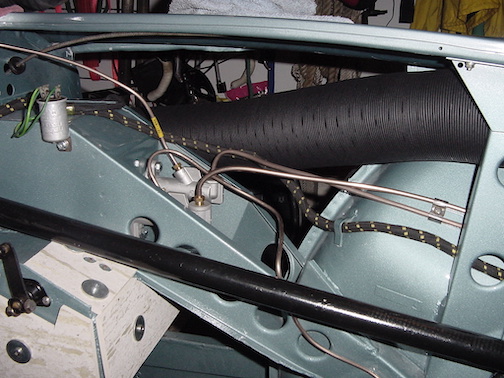
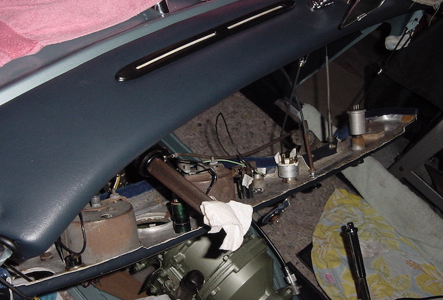
Bonnet Release Rod: The bonnet or hood release rod is inserted
from inside the cockpit side and slide on the firewall grommet and
the spring adjuster onto the rod as it goes through the bracket on
the side. The end is connected to the lever with a washer and
cotter pin. I put some Teflon lubricant on it where it goes
through the grommets so that it slides more easily. You can also
see in the second photo the 2 relays that control the headlights.
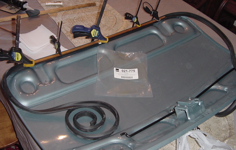
Boot Lid: Working on the boot, or trunk, lid. Installed the prop
rod with a new grommet and new rubber clip, and attached the
emblems with the spire nuts. The rubber gasket has to be glued on,
am trying silicone glue and will see how that works. I don't know
what they used originally but it is a pain to have to clamp the
gasket in place until the glue dries, and then move along a
section at a time to get it all glued down.
Convertible top snaps: These are called Tenax fasteners for
attaching the soft top. I used the originals and cleaned them up
and got some nickel plating solution to improve the color as they
looked more brass than silver. There are little leather washers on
the outside so I got new ones for those and used most of the
original metal washers and nuts underneath.
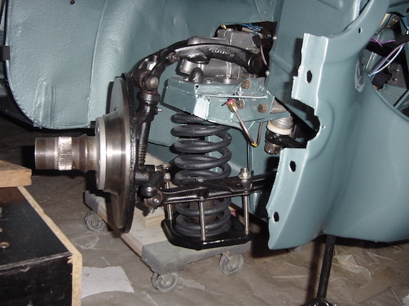
Front Suspension: I bought new kingpins and had a machine shop
replace and ream the bushings in the swivel axles and the kit came
with various new washers and lower fulcrum link pins and bushings.
The new king pins used big nylock nuts on top and were not drilled
for the cotter pins. I squeezed the various rubber bushings onto
the lower link arms and upper trunion, but everything was still a
pretty tight fit, finally wiggled everything into place. Had to
spread out the 2 shock arms a bit to squeeze the upper trunion
bushings into them but everything finally fit. Put in the 2 inch
block under the shock arm and tightened up the bolts and cotter
pins where applicable. One of the new inner lower link fulcrum
pins also came with a nylock nut rather than a cotter pin. I will
be using the long bolt method to install the front coil springs.
Don't forget to put the roll bar plates in place on top of the
front lower link arm before putting the bolts through for the
spring plate. Tighten up the long bolts then replace one at a time
with the ones that are supposed to be there. Photo shows the long
bolts before tightening them up to compress the spring.
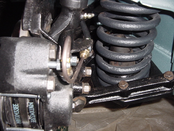
Front Brakes: Today I installed the front brake calipers which
had been rebuilt with new stainless steel pistons. Be sure to push
the pistons all the way down into the caliper body because the
brake pads are a tight fit once the caliper is bolted onto the
swivel axle, especially with new brake discs. The brackets for the
brake hose bolt onto the studs. Next I wiggled the brake pads into
place and the little stainless steel shims taking care for the
arrow showing direction of spin for that wheel. The pins and
little cotter pins hold the pads in place. Next, the brake hoses
were screwed onto the brackets. The short pipes from the hose to
the caliper have to be bent to shape and then installed. Now the
whole brake system is in place, but I will wait to add fluid until
later in the assembly. You can also see the coil spring in place.
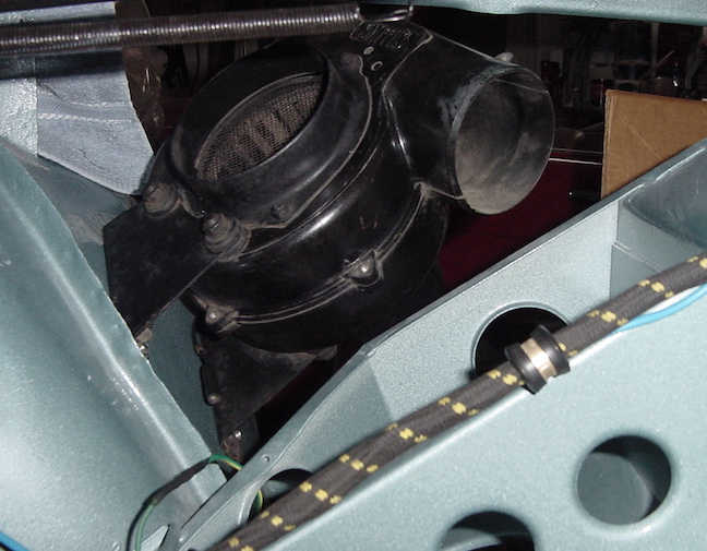
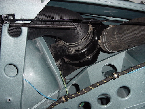
Heater Blower: Today I bolted the heater blower onto the right
inner fender using some fender washers and 1/4 inch screws. The
ground wire had a ring terminal and was secured under one of the
nuts on the inside. I had to rotate the fender washer back and
forth to get it to break through the paint and make a good contact
with the metal fender to get a good ground connection. Haven't
connected the air ducts yet, they seem to get in the way of
accessing the fender screws, but the fenders get in the way of
attaching the ducts, creating a dilemma.
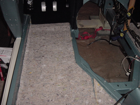
Carpet insulation: This underlayment has a foil side on the bottom
and the fiber side showing. This was cut to size and lightly glued
onto the floorboards, making sure to cut the holes for the seat
attachment bolts and marking the position for the other screw holes
for the carpet snaps.
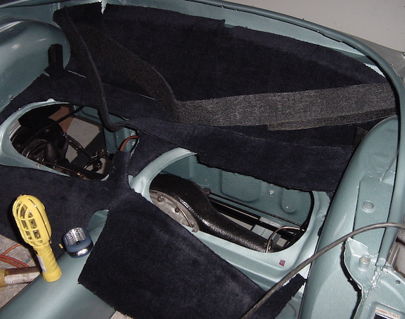
Rear area carpet: These pieces of carpet had to be trimmed to fit
the rear area around the back seats, and the heelboard. Haven't
glued them on yet, but have cut out the holes for where the seats
screw down.
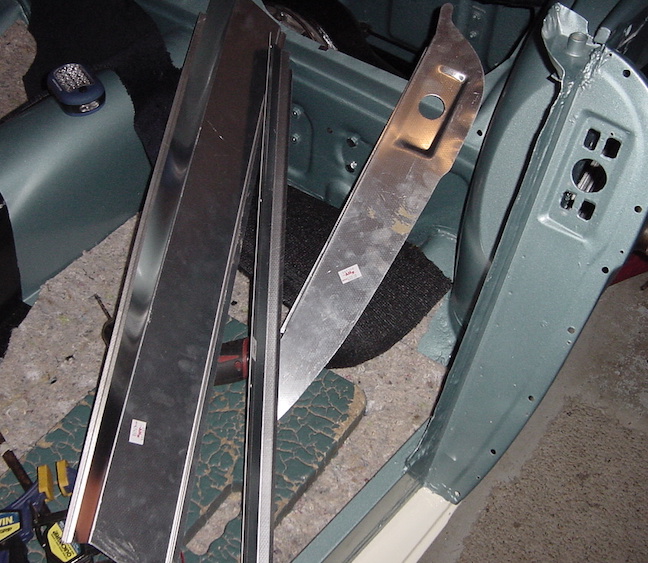
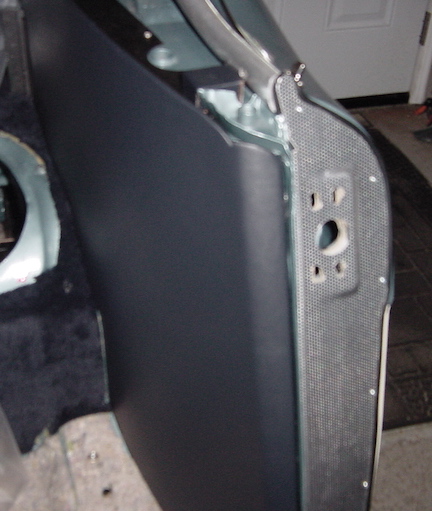
Aluminum doorway trim panels: Even these panels had to be
modified some to fit correctly. The bend in them was too tight so I
had to unbend them some to fit the contour of the rocker panels.
Then I had to use a file to tweak the ends to get them to fit in the
corners. I clamped them in place to drill the holes for the door
latch, and for the little trim screws that hold them in place. The
rear fenders have to go on first before these can be permanently
attached.
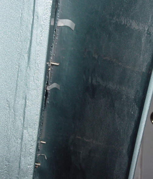
Attaching rear fenders: The rear fenders were the originals that had
been repaired with the patch panels welded in place and smoothed in.
Since the door pillars had been replaced new holes had to be drilled
for the screws to attach there. Before assembly, the sticky anti
corrosion strip was stuck onto the body side and holes poked out for
the screws. The chrome trim strip was taped onto the fender and the
tabs bent over so it stayed in place enough to attach the fender.
The chrome strips had to be bent to fit the curved contour and care
must be taken to avoid kinking them. I had an assistant to hold the
fender in place while I put in enough screws to keep it in place.
Some of the screws were pretty hard to reach but just managed with a
7/16" combination wrench or a socket. As I went around and tightened
the screws, I tweaked the position of the fender and the chrome trim
to get them snug and in the right places. The right photo shows
inside the fender where the tabs are bent over to hold the chrome
strip.
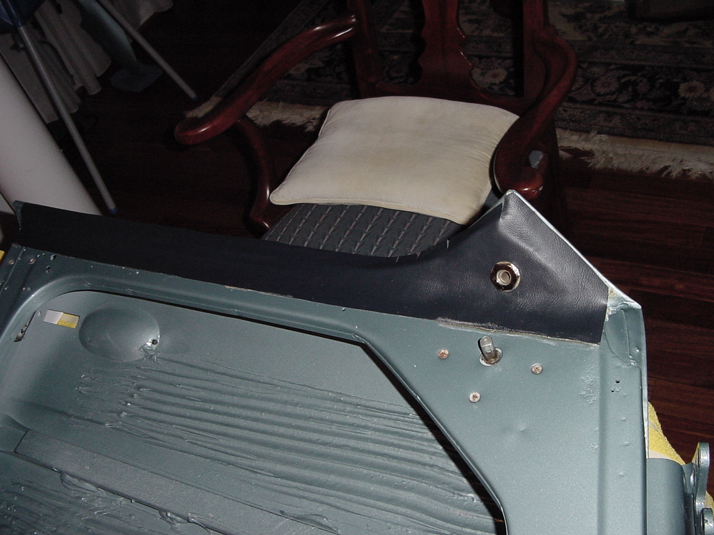
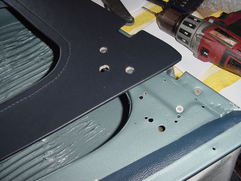
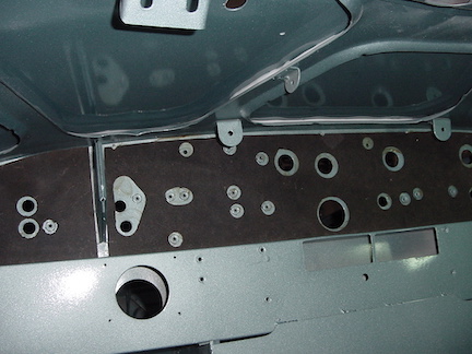
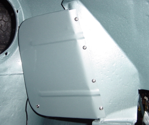
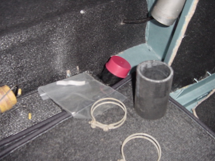
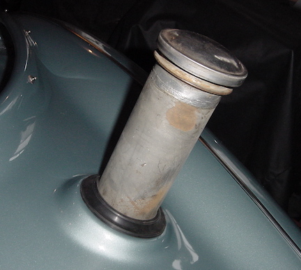
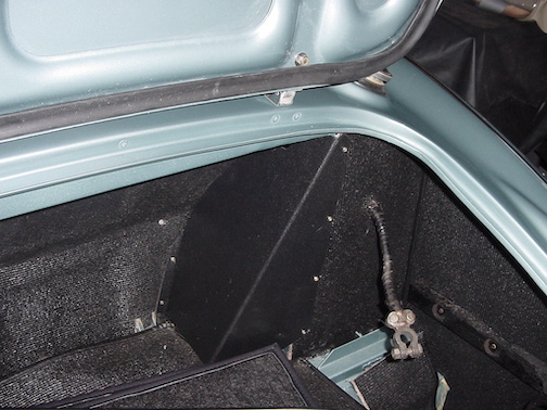
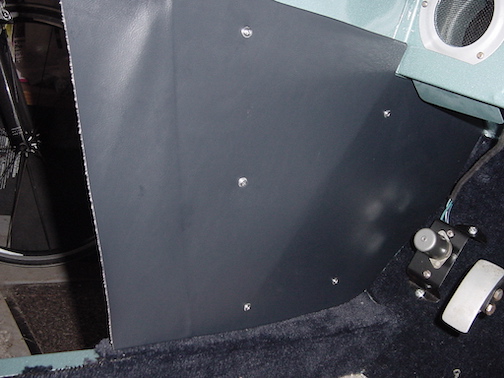
Gas filler and boot area: The boot lid has already been prepared
with the foam rubber weather strip glued in place, hinges attached,
and release handle installed, plus the support rod and the
decorative emblems. The gas tank filler tube goes in through a big
gasket set in place first. A length of rubber hose attaches the
filler neck to the spout on the tank, secured by 2 wire clamps.
Photo shows condition before assembling, and then the finished boot
area. The black panel hiding the filler tank is screwed in place,
and I had to poke a pin through the holes from behind to locate them
so I didn't have to drill new holes.
Footwell side panels: These panels are held in place with 5 screws.
I had replacement panels so they didn't have the holes for the
screws. Not wanting to drill extra holes in the metal, I was able to
poke a pin through the holes from the outside through the panel so
locate where to place the screws. The panels fit well and there was
a flap of the vinyl material that was glued to the edge of the
doorway opening.
Heating Ductwork and Front Fenders: Two of the screws for the front
fenders are behind the big air ducts and are hard to reach, but it
is hard to put the ducts in place with the fenders already on, so
the order of assembly is difficult to decide. Here is what I finally
decided.
1. Install the left side fresh air duct. It is just possible to get
a hand around this duct to place the screws on the left fender. Wait
to install the left fender until the engine in in place to allow
easy access to the exhaust manifold and pipes.
2. Put the 2 heater ducts in place on the right side, but don't put
the heater blower in yet. Then I can reach in the space where the
heater blower goes to tighten those 2 screws, and then put in the
heater blower and attach the ducts after the right fender is
installed. Still working on this so will update depending on how
this works out.
If using new ducts, make sure to stretch them out to a little over
the needed size first and then squeeze them in place, much easier
than trying to stretch them once in place.
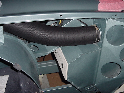
I ended up putting the heater blower box in place, then put the
fender on, letting the box slip down so I could reach the 2 screws
behind the blower and ductwork, then attaching the air ducts and
then screwing the blower box down in place.
Rear trim Panels: These slip under the slots on the sides, and the
front wood bar is screwed to the door pillar with 4 wood screws.
There are a couple of screws on top of the metal panel, one screws
directly in and the other is in the wood block covered with the trim
material. Sorry for the blurry photo.
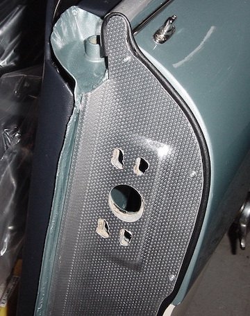
Aluminum Door Trim Panels: These go on after the rear fenders are
attached and the rear inside trim panels are attached. They did need
a little trimming at the ends to fit the door opening. Since there
were already holes for the screws in the fender, I held them in
place and marked where the holes should be from inside the fender so
as to not have to drill new holes through all 3 layers of metal. The
welting is held down by the screws, and the core is removed from the
top bit that wraps around the tongue at the top to make it turn the
corner easier. I also cut out some V shaped pieces to help it make
the bends.

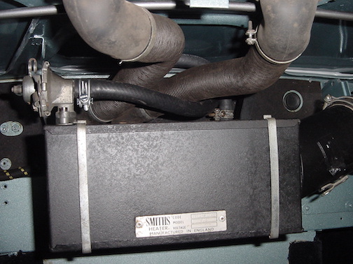
Heater Box: This is screwed on under the dash area. I attached the
hoses first to make that easier. The coolant hoses cross so the hose
from the valve on the heater box goes out on the right side and
leads to the valve tap on the cylinder head.
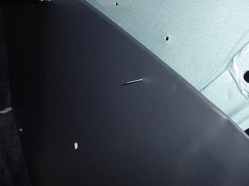
Padded Dashboard Top: This was new so had to have the holes drilled
for the tonneau fasteners and the screws that hold down the 2 ends.
It was predrilled for the demister and mirror and those holes lined
up pretty well with the holes in the body. I had to cut out the
padding and vinyl for the demister outlets, and then attach the
demister vent covers and the mirror. The wood was fairly straight
and still so I softened it up a bit with some steam on the wood side
and clamped it with a bend and that helped it fit better. The right
hand fender was already on the car so next I attached the rubber
scuttle seal with the copper split rivets. One flap of this fits
under the padded dash top, so I wasn't able to finish the left side
since that fender is not on yet. A little strip of the beaded
welting fits between the dash and the rubber scuttle seal. (The
white spots on the fender are just light reflections, not scratches
thankfully.)
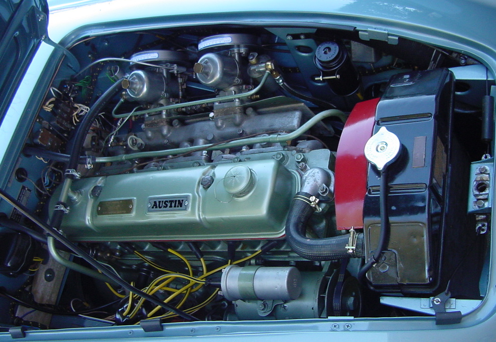
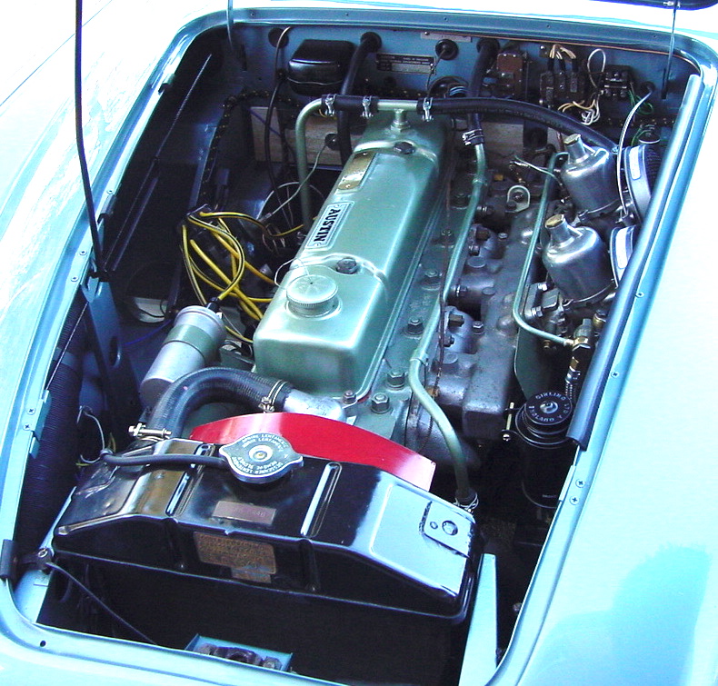
Engine In! Had my son and another friend here today so was able to
get the engine put into the car. My engine lift crane has an
adjustable boom and I had it extended all the way out and still was
unable to reach with the crane in front of the car so we moved to
the side of the car and it was able to reach. I had the engine
suspended so the back end was a few inches lower than the front and
that helped clearing the obstacles. They really made the engine a
tight fit and I had already removed the generator and distributor
for more clearance. Once we lowered is carefully and had it close,
we used a roller jack to lift up the back end of the engine to level
it out and get the front pulley past the cross member. Pay close
attention to the steering column as the motor mount and the heat
shield need to get past it. Also watch the brake pipes on the right
side of the car, the electrics on the firewall, the generator mount,
and the front pulley.
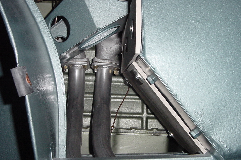
Exhaust Downpipes: These were installed from the side as I had not
yet attached the left fender. They have a copper clad gasket and use
brass nuts. Other items not pictured include attaching the coolant
hoses to the heater, and reinstalling the generator and distributor.
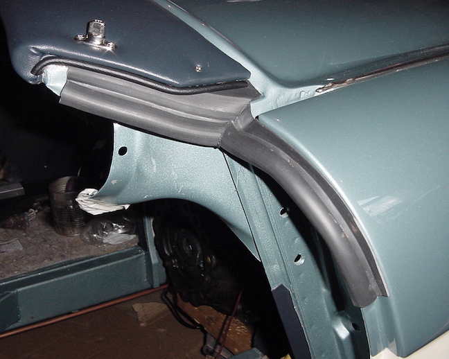
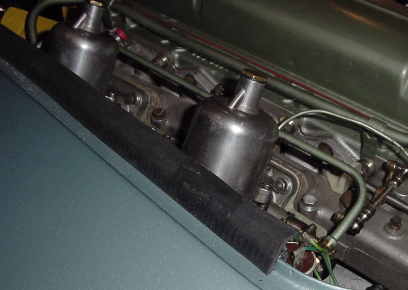
Hood buffers: The long strip buffer just presses on to the left
side, and the 3 small buffers on the right side attach with the
copper split rivets and copper washers. Also in this photo is the
accelerator shaft attached with the white plastic bracket to the top
of the intake manifold with the other end going to the bushing
grommet in the firewall.
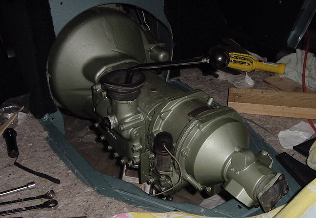
Gearbox (transmission) installed: Had a couple of guys here to help
me put the gearbox in. Seemed harder than it should have been. Start
with the brackets at the rear end removed. The assembly was lifted
into the cockpit at a slight diagonal and back the end into the
tunnel. Use a floor jack to support the weight of the gearbox. I
also used a little bottle jack to slightly lift the back end of the
engine since the motor mounts don't quite hold the back end of the
motor up to the right height. After backing the overdrive end into
the tunnel there was room to swing the bell housing roughly into
place. (We had a piece of plywood covering the opening in the floor
of the car until the bell housing was in position, then we raised
the floor jack and slid out the plywood and supported the gearbox
with the jack.) It took several hands to keep the unit balanced on
the jack and then carefully lower it into alignment with the
flywheel. We had to rotate the shaft a little to line up the splines
and then wiggle it forward and get some bolts in place. Once
everything was in place the bolts were tightened down. Then the rear
mounting brackets were bolted onto the back end of the overdrive and
onto the chassis, and the engine motor mounts were also given a
final tightening. There is a tie rod and bushings that attach the
loop underneath the overdrive to the frame.
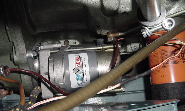
Starter Motor: One of the concessions to modern technology that I
allowed was to get the new gear reduction starter. It has a mounting
plate on the front with set screws that allow it to mount in
different rotational positions, but none of the options allowed it
to fit so I had to drill 2 new holes in the plate to make it fit,
and even then it was a tight squeeze. The other thing in the photo
was an oil filter adapter that allows you to use a regular spin on
oil filter instead of the original canister type.
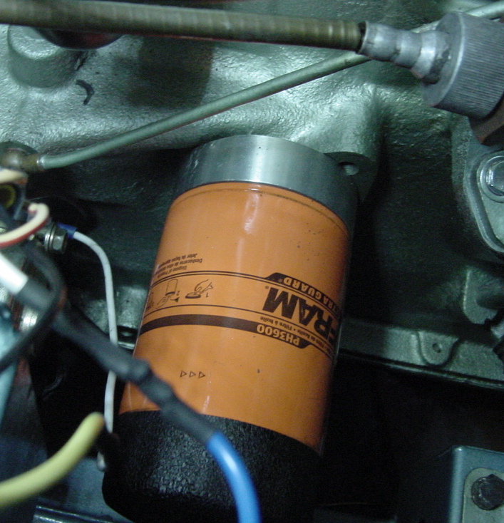
Close up of Oil Filter adapter: Spin on oil filter adapter from Moss
motors, makes it easy to change the filter, and less prone to leak
than the original oil filter. Just bolts on to the original tapped
holes so no permanent modification and original filter saved for
posterity. The upper left edge of the adapter contacted the casting
on the engine block, so I actually had to file a tiny bit off the
edge of the adapter at that spot. I tried putting it on 180 degrees
so it looked like it should fit better, but the oil holes didn't
line up properly so this was the orientation that was necessary for
it to work right.
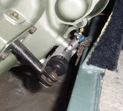
Clutch slave cylinder: This just bolts onto the bell housing and
connects to the clutch hydraulic line. There is supposed to be a
rubber boot over the lever so I will have to add that later. You can
also see the grounding strap that connects the bell housing to the
frame for electrical conductivity.
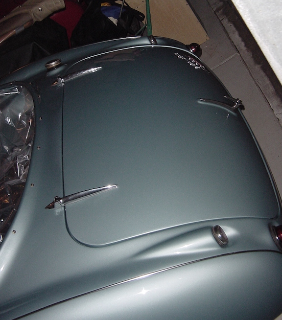
Bonnet On it: Had some helpers to help put the bonnet (AKA hood in
the US) on. The hinge levers attach to the pockets with some clevis
pins inserted from under the dash. Then you have to make sure to
have one flat washer and one wavy washer on each side of the pin
before you put the cotter pin through the hole. This requires
squeezing the flat washers in order to flatten the wavy washers to
be able to insert the pin. I ended up grinding one of the flat
washers thinner in order to be able to get the cotter pin through.
The hinge bolts onto the brackets on the bonnet, and then you have
to adjust the position of the hinge within the slots on the bracket
to get the bonnet into the right position up-down and front-back. I
also had to adjust the spring release at the front of the bonnet to
get it to catch and release smoothly.
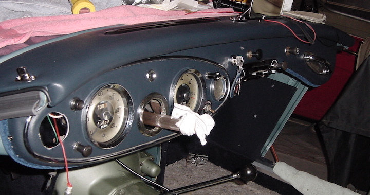
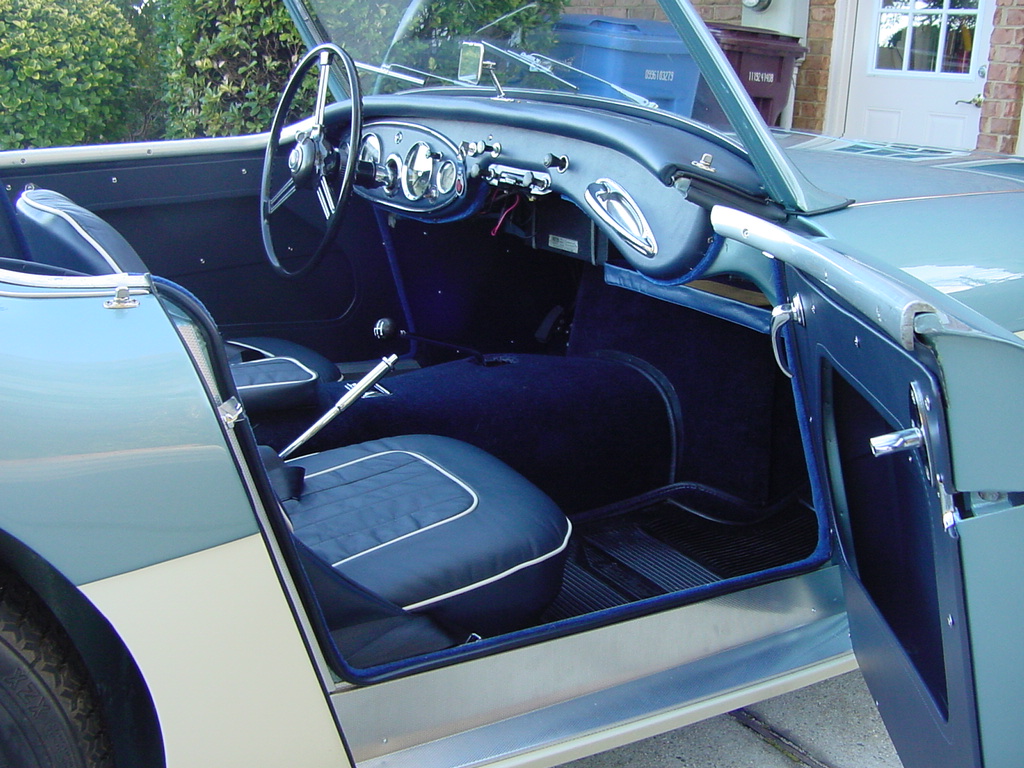
Instrument Panel: I hung the preassembled panel on some bungee
cords so I could wire up the instruments before bolting it on so I
didn't have to spend so much time on my back looking up under the
dash. I had one short when I applied power. One of the wires to the
headlight switch was in contact with the bracket on the fuel gauge
that holds little light bulb and created a dead short. I rearranged
the positions of those items to fix the short and everything seemed
fine, but the bulb in the fuel gauge was blinking on and off. I got
up under there and replaced that bulb, and turns out that bulb was a
blinking bulb, with the little blinker strip inside the glass! I
don't know where that came from but replaced it with a correct one
and works fine now. The instrument panel bolts on with 4 screws.
Oil pressure and Temperature gauge: This was installed after the
dashboard was in place. The thermometer sensor screws into the
cylinder head near the front of the car and is permanently attached
to the gauge, with the grommet that fits in the firewall. Once you
get the sensor threaded through the hole in the instrument panel and
over the heater, through the firewall you can get it into position
to screw it in. I think it made about 4 revolutions once it was
threaded and I had put one reverse loop into the capillary tube and
then as it turned you have to make about 3 more loops up near the
firewall to take up the twist and slack in the tube.
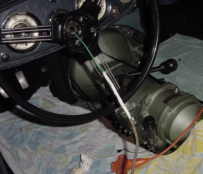
Steering Wheel: Most Healeys had the adjustable steering wheel that
slides onto the column, with a little pushing, make sure to put on
the chrome springy coil and collar first. I had already put in the
long tube down the column so had to thread the wires down through
that. I slid a stiff insulated 14 GA solid copper wire up the tube
from the front and then taped the wires onto that and pulled the
wires out the front. I had to cut off the little bullet connectors
first so soldered new ones on after it was in place. It is a pretty
snug fit getting the wires down through the tube.
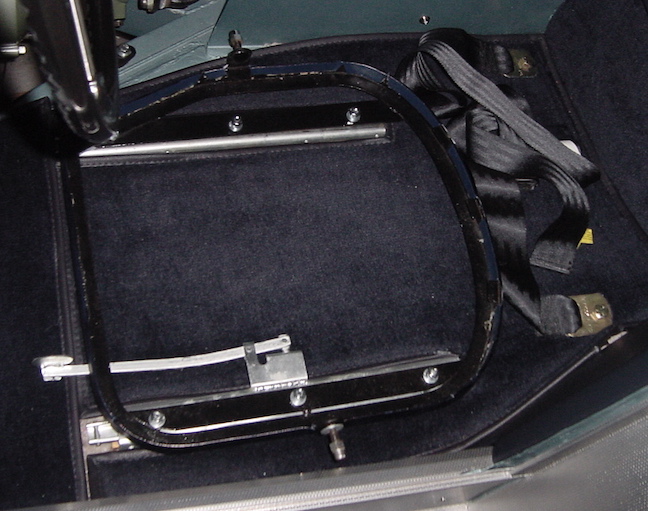
Front seat bases: The sliding rails sit on top of the wood
spacer strips and are bolted on with the T nuts from underneath. I
had the original floor pans so didn't need to drill any holes. The
base frames then bolt on to the sliding rails. The outside stud for
the seat back was very close to the side panel so it will be
impossible to unscrew the acorn nuts without loosening the seat base
frame off the sliding rails, then attach the seat back and acorn
nut, then bolting the base frame back onto the sliding rails. That
seems to work. You can also see where I installed the seat belt
anchors through the floor pan.
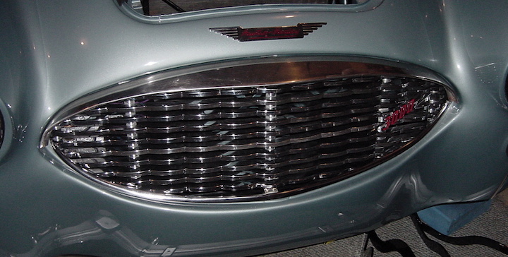
Front Grille: The front grill can be wiggled in from the front with
the radiator air deflectors detached at their bottom connections.
The three tabs at the top are held in by bolts from behind the
shroud, through the grille tabs and into the threaded holes in the
chrome top cowl. The two outer lower tabs bolt to the shroud and
also hold the radiator air deflector and the braces for the splash
guards.
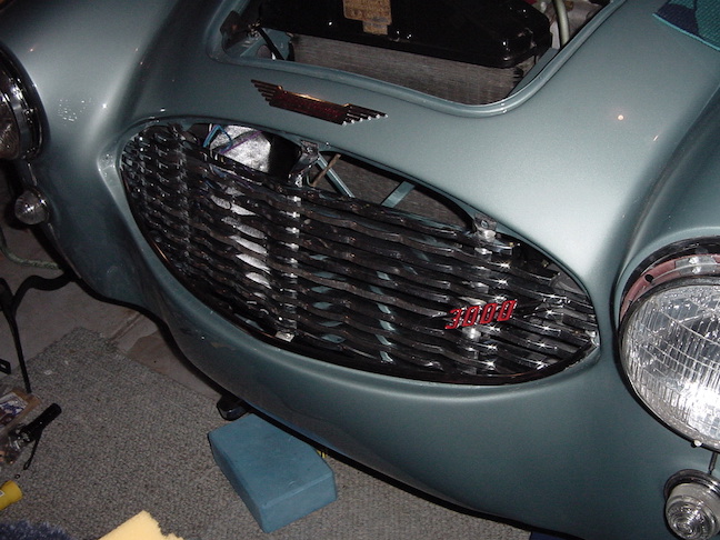
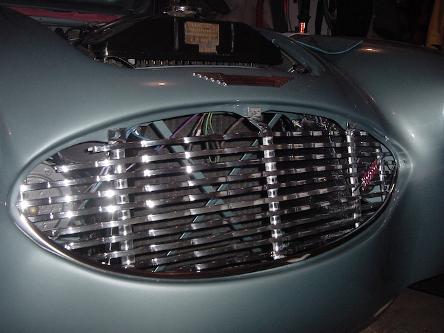
Now the top cowl is installed.
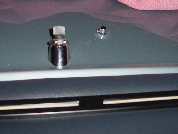
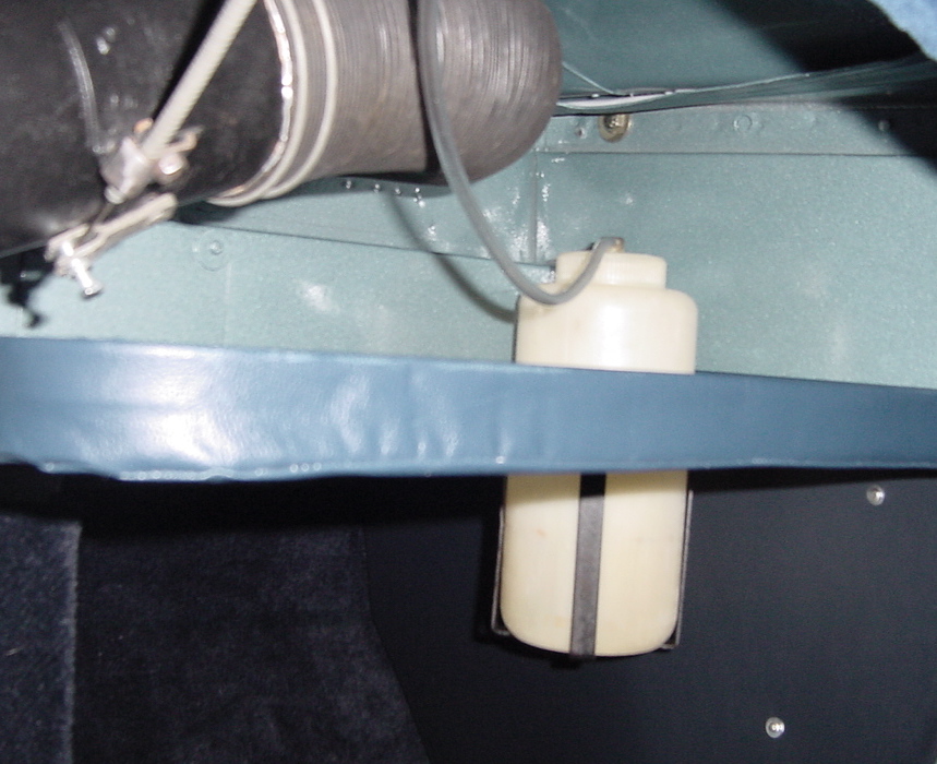
Windscreen washers: The jets attach through the shroud and best I
can tell they point outward with the tiny hole aimed at the
windscreen. The tubing then connects to the pump and reservoir.
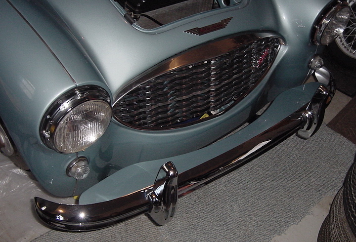
Front Bumper: The bumper bar is a new one, and after trying on the
brackets, they turned out to be so bent out of shape I had to buy
new brackets, or spring bars, too. I also got a new splash
apron and that has been painted body color by the paint shop. The
slots in the splash apron didn't line up with bolt sockets in the
bumper so I had to modify two of the slots with a grinder to get
them to fit. I also had to slightly modify the bolt holes in the
bracket where they bolt onto the frame to get the brackets to clear
the bottom of the front shroud. When that was done, I loosely bolted
the brackets onto the frame, then placed the apron on top of the
brackets with the front edge of the apron over the front of the
brackets. Then the bolts go through the holes in the brackets, the
slots in the apron and into the bumper. A bit tricky to push and
shove the bars in place to get everything to line up, but finally
got everything together and tightened up all the bolts. The gap from
the apron to the shroud seems a bit wide, but will live with it.
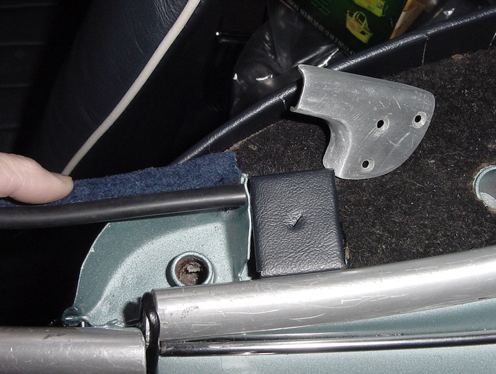
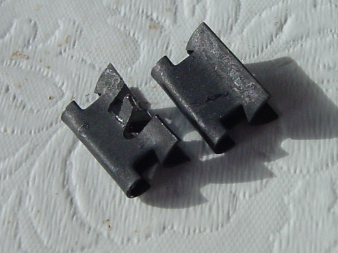
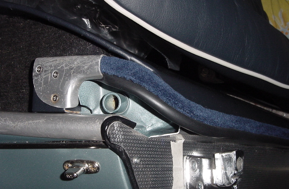
Fuzzy door seals: Variously called Furflex or Bristleflex, this
strip runs all the way along the door opening. I think originally it
was just pressed onto the rim of the opening but now they sell
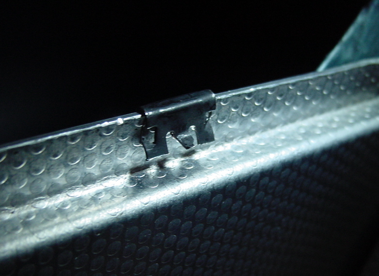
little clips to help it stay in place. Even with those clips, it
still didn't seem to catch hold of the aluminum strip and I ended up
modifying the clips, making the legs shorter and creating a little
tab to stick out and catch the trim piece. Even with the modified
clips, it was difficult to get the strip to press in to the corners
and stay put, but seems to finally looking OK now. I started at the
rear and worked my away down and forward and then the little
aluminum cap holds down the back end where it was started.
Windscreen on: Today I put the windscreen on the car, aka
windshield. Should have been easy, but was difficult to push the
windscreen assembly down far enough to get the holes in the body to
line up with holes in the windscreen posts. Since the body
shop had the shrouds off I think they were replaced a hair too high.
Anyway, I managed to get it bolted back on and will put on the
wipers after I make sure they are in their "parked" position.
Really starting to look like a car now.
Car is mostly put together now. Need to add coolant, or water
to start with, to the radiator and check for leaks, then get the
ignition timing in the ballpark enough to at least get the engine
started. Then I will purge out the fuel lines to get rid of any
debris and then hook the fuel lines back up and check for fuel
leaks.
Other items still on the to do list include: Set the toe-in on the
front suspension, install transmission tunnel and carpet, assemble
convertible top, and tune up engine once it is running.
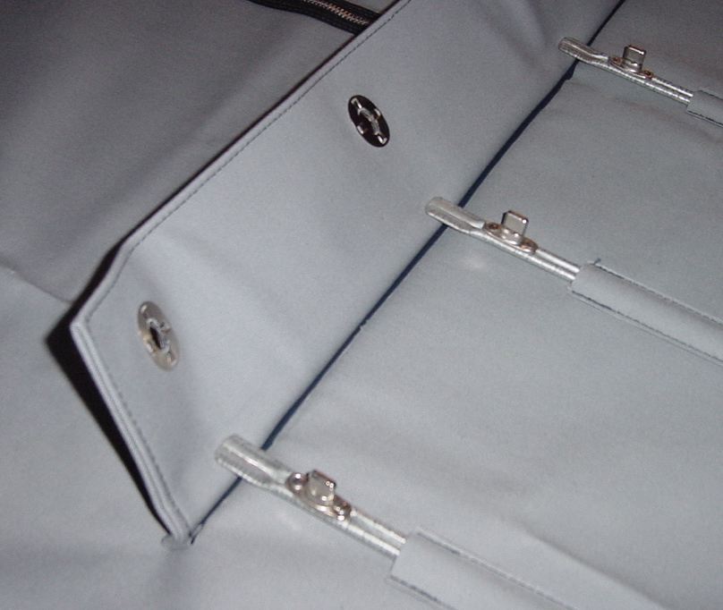
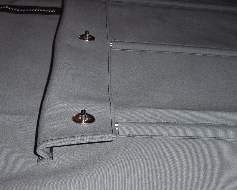
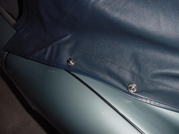
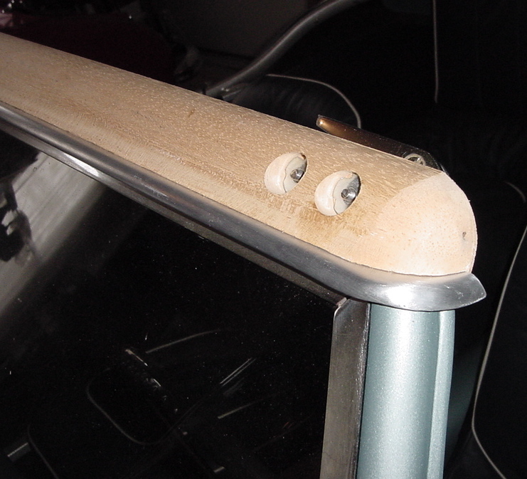
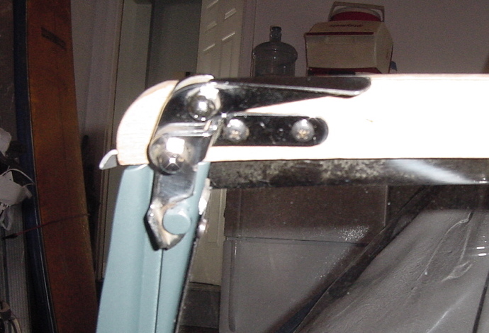
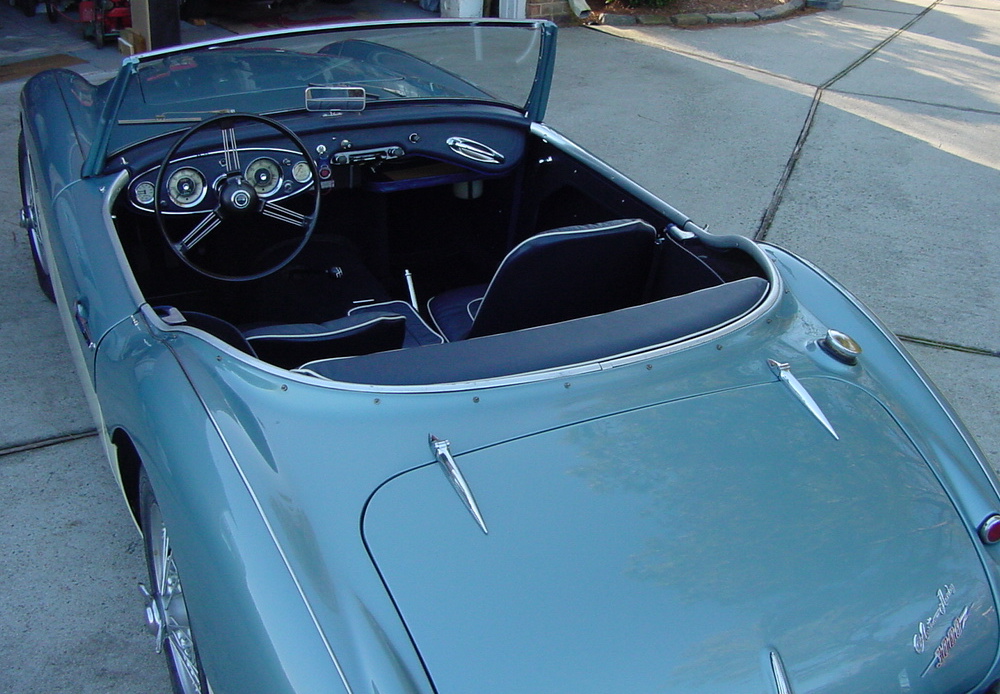
Tonneau Cover: I had ordered the blue tonneau cover and convertible
top cover several years ago. The tonneau came with the Tenax
fasteners already installed and they fit correctly. It was a slight
stretch to get the dashboard snaps to fit, but was able to get them
to fit. I bought new tonneau stiffener bars and I thought that they
were too long, but I found on the Moss Motors webpage a description
of how the stiffener bars were supposed to fit. See photos below, as
the bars extend over the sewn seam and the flap folds down over the
end of the bar in what looks like an unusual configuration, but the
turnbuckles fit right like they are supposed to and the extra fold
in the flap reinforces the top layer of the tonneau to help prevent
the end of the bar from poking through. So don't cut off the ends of
the bars to help make them fit.
Dec 24, 2020: Got the engine running over the past few days. A
little trouble initially getting the timing and carb settings in the
ballpark to start it up, but managed. I noticed that the tachometer
is not working so may need to get a new cable for that, hopefully
not the tachometer itself, but I had tested it with a drill and
seemed to work prior to installation.
Convertible top: The top needs to be assembled and the Tenax snaps
need to be installed. I put on the frame support and attached to
aluminum rail to the underside of the wood bow and attached the
clamps. then draping the top over the frame put the top in position
and started installing the Tenax snaps. Punch a 5/16" hole in the
right spot and spin on the snap and tighten with the little tool.
Still in progress at this point and might wait until spring and work
on it when it warms up. they say if you stretch it outside on a warm
sunny day, the material stretches better and you get a more snug
fit, so just doing the snaps for now.
Working out some kinks: Got the engine started but no test drive
yet, trying to get the engine tuned up some. Timing is set pretty
well now and I think the carbs are set somewhere in the ballpark to
sound decent, but tuning them is sort of by ear. Will note some
problems and actions taken below.
Tachometer needle bouncing up and down. I
can hear intermittent clicking noise in the tachometer as well.
Action taken: Installed new tachometer cable and works normally now
with stable reading and no noise.
Choke control nearly impossible to pull out: This
was the original control cable and was pretty badly kinked up in a
few places, also looks like it had been cut and was a hair short so
barely able to secure it in place. Bought a new cable that comes
with the knob already attached. These are supplied with about a foot
of extra length, so had to be trimmed down to size, carefully so as
to not make it too short again. Installed, trimmed, tightened up the
secure points and operates smoothly now.
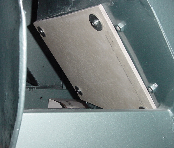
Clutch won't disengage: This was a tough
problem and still not sure I am done with it. Car has new clutch
plate, release bearing, and all new clutch hydraulics
including master and slave cylinders and all pipes and hoses. System
was bled and rebled. Pedal stops about an inch from the floor so not
getting full excursion of the slave cylinder. From resting position,
I noted that I could push the push rod back into the slave cylinder
about a full inch so it was starting its action about half way
through its full travel. When I bought the car as a barn find
project, it came with a gearbox that has a BN-4 tag on it, so
obviously the original gearbox was swapped out at some point with
and older one. The older one had a slightly different bell housing
and used a 9.5 inch diameter clutch. My engine is original to the
car and used a 10 inch diameter clutch. That bell housing is not
compatible with my engine, as the pressure plate didn't fit inside
the bell housing in particular on the casting by the clutch fork.
Turns out previous owner had shaved off enough metal to get the
pressure plate to clear the bell housing, just barely. Must have
also been a slight difference in the distance from the clutch fork
to the pressure plate release bearing surface with this mismatched
set up compared to the original. Anyway, I ended up fabricating a
new slave cylinder push rod about 3/4 inch longer than the stock one
and clutch releases normally now. Still waiting for a road test, so
the final word is not in yet on this issue.
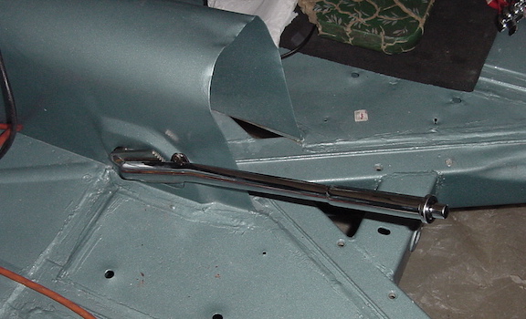
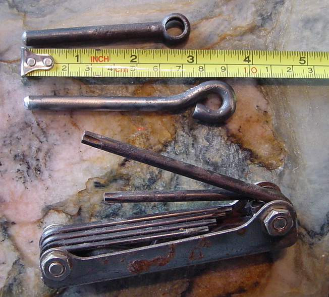 So here is a
photo of the fabricated pushrod and the donor Torx tool set.
So here is a
photo of the fabricated pushrod and the donor Torx tool set.
Waiting to install the tunnel cover until after a
road test in case I need to do any more work there.
Got the slave cylinder push rod installed and tested OK, shifted
very smoothly and snychro worked well in 2, 3 and 4th gears. First
test, the rod was a bit too long and the clutch released quite high
and something scraped when the pedal was all the way down, so
shortened it up about 1/4 inch and that seems to be about right.
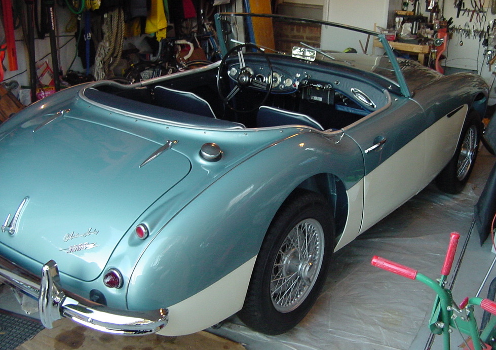
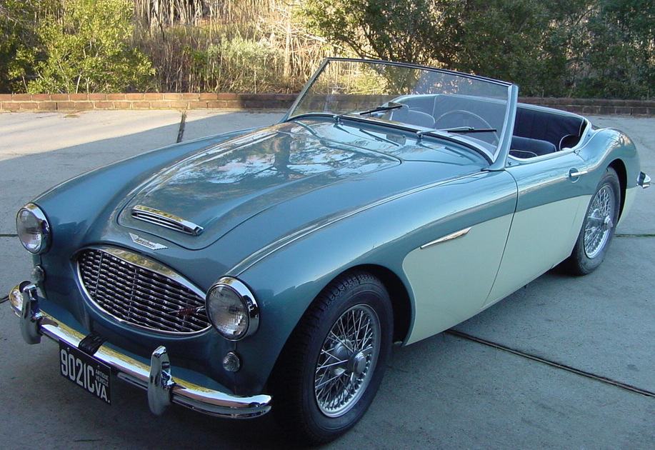
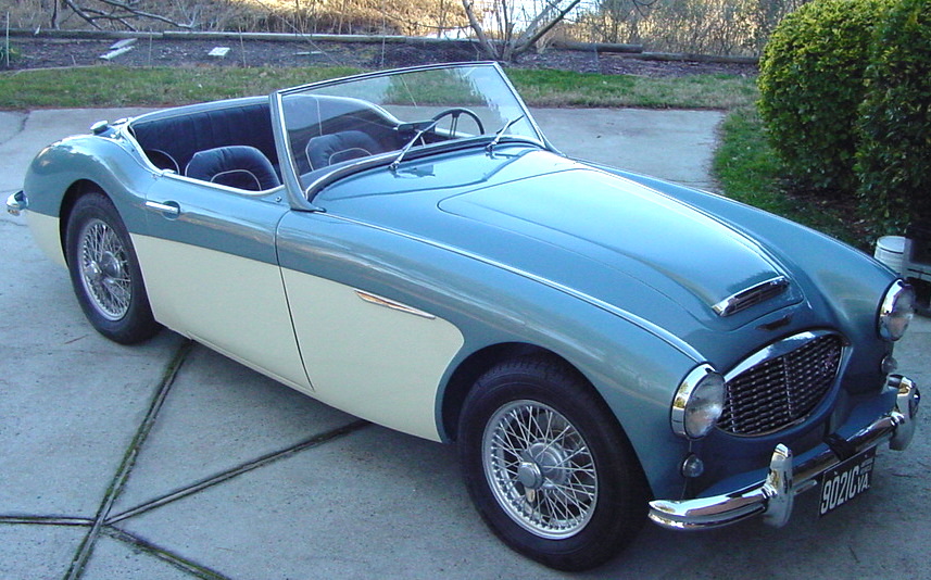
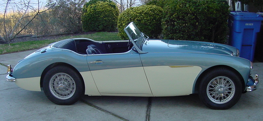
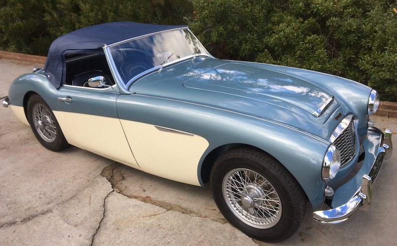
Finally getting it out of the garage so here are some photos of the
nearly finished car.
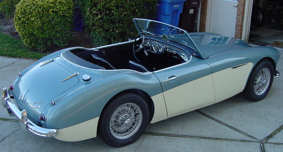
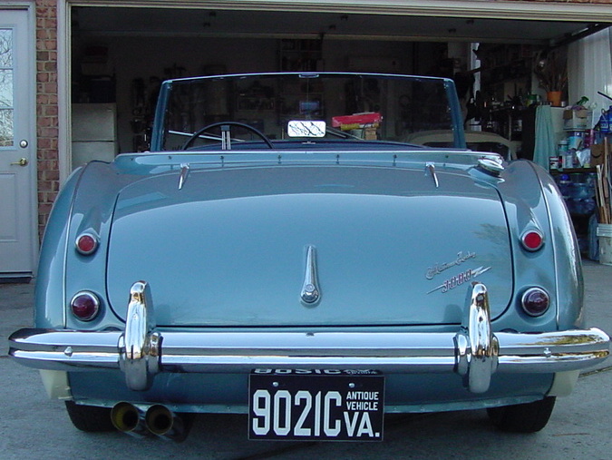
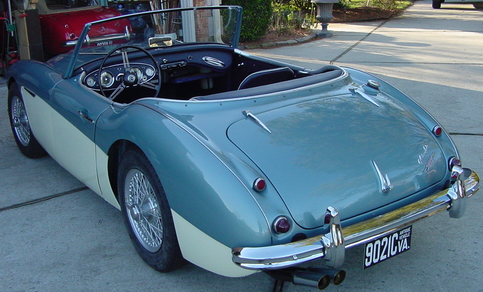
Finally got the convertible top installed,
Back to
Scott's Crystal Radios